机器人建模、运动学与动力学仿真分析是机器人设计和开发过程中的关键步骤。
一、机器人建模
机器人建模是描述机器人物理结构和运动特性的过程。其中,URDF(Unified Robot Description Format)是一种常用的机器人模型描述方法。通过URDF,可以定义机器人的连杆(links)、关节(joints)、惯性(inertia)、视觉和碰撞属性等。
- importrobot
- 功能:
importrobot函数用于从URDF(Unified Robot Description Format)文件中导入机器人模型。URDF是一种XML格式,用于描述机器人的关节、连杆、碰撞和视觉属性等。 - 使用方式:通过向
importrobot函数提供URDF文件的路径,可以创建一个rigidBodyTree对象,该对象包含了机器人的所有物理特性和运动学特性。 - 示例代码:
robot = importrobot('myRobot.urdf');
- 功能:
- loadrobot
- 功能:
loadrobot函数用于加载预定义的机器人模型。这些模型可能是MATLAB Robotics System Toolbox中已经内置的,或者是用户通过其他方式定义的。 - 使用方式:通过向
loadrobot函数提供一个字符串参数(表示机器人模型的名称),可以直接加载该模型为一个rigidBodyTree对象。 - 示例代码:
robot = loadrobot('universalUR10');// 加载Universal Robots UR10机器人模型 - 特点:
loadrobot函数提供了一种快速访问常见机器人模型的方法,无需手动编写或导入URDF文件。
- 功能:
- smimport
- 功能:
smimport函数通常用于导入CAD(计算机辅助设计)文件或其他3D模型文件到Simscape Multibody环境中。Simscape Multibody是MATLAB的一个模块,用于构建和仿真多体系统(如机械系统)。 - 使用方式:
smimport函数支持多种CAD文件格式(如STL、STEP、IGES等),允许用户将CAD模型导入Simscape Multibody环境中进行进一步的处理和仿真。 - 特点:虽然
smimport函数可以用于导入机器人模型,但它通常更多地用于导入更一般的3D模型。与importrobot和loadrobot不同,smimport不直接创建rigidBodyTree对象,而是将模型导入到Simscape Multibody环境中,以便进行更高级的动力学和运动学仿真。
- 功能:
importrobot:从URDF文件中导入机器人模型,创建rigidBodyTree对象。loadrobot:快速加载预定义的机器人模型为rigidBodyTree对象。smimport:将CAD或其他3D模型文件导入Simscape Multibody环境,通常不直接创建rigidBodyTree对象,而是用于更复杂的动力学和运动学仿真。
在MATLAB中,可以使用importrobot函数来读取URDF文件并创建机器人模型。
在MATLAB中,使用loadrobot函数加载机器人模型并将其表示为rigidBodyTree对象后,您可以进一步将这个模型转换为Simscape Multibody模型,以便在Simulink环境中进行更复杂的动力学仿真。
robot = importrobot('universalUR5e.urdf');
show(robot)robot = loadrobot("universalUR5e",DataFormat="column");
robotSM = smimport(robot,ModelName="ManipulatorTrajectoryPlanning_Subsystem");
model = get_param(robotSM,"Name");
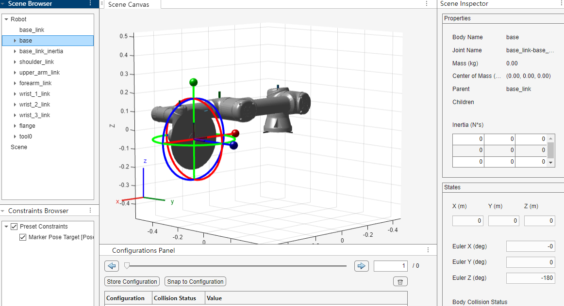
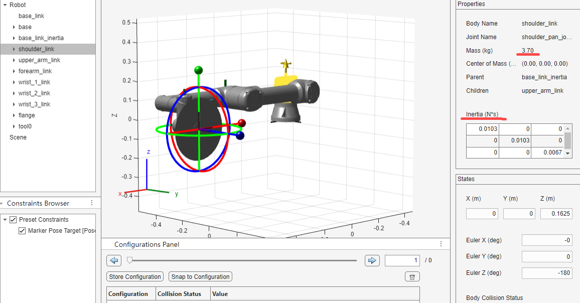
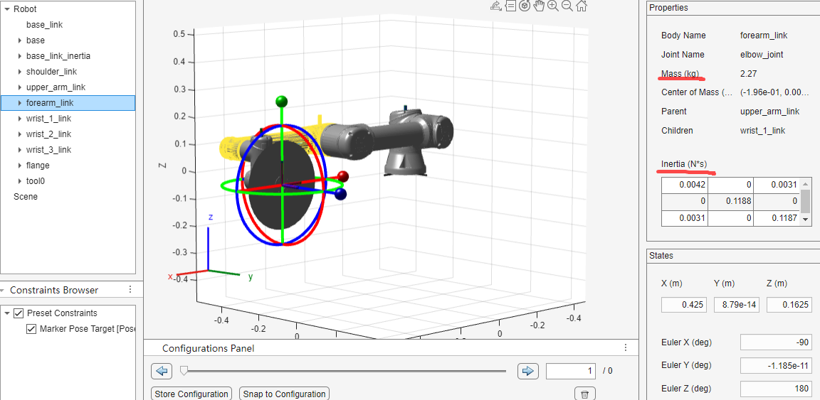
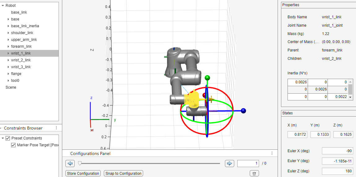
% 导入UR5e机器人模型robot = loadrobot("universalUR5e", "DataFormat", "row", "Gravity", [0 0 -9.81]);show (robot)% DH参数a = [0.00000, -0.42500, -0.39225, 0.00000, 0.00000, 0.0000];d = [0.089159, 0.00000, 0.00000, 0.10915, 0.09465, 0.0823];alpha = [1.570796327, 0, 0, 1.570796327, -1.570796327, 0];q_home_offset = [0, -1.570796327, 0, -1.570796327, 0, 0];joint_direction = [-1, -1, 1, 1, 1, 1];mass = [3.7000, 8.3930, 2.2750, 1.2190, 1.2190, 0.1879];center_of_mass = [[0, -0.02561, 0.00193]; [0.2125, 0, 0.11336]; [0.11993, 0.0, 0.0265]; [0, -0.0018, 0.01634]; [0, 0.0018, 0.01634]; [0, 0, -0.001159]];
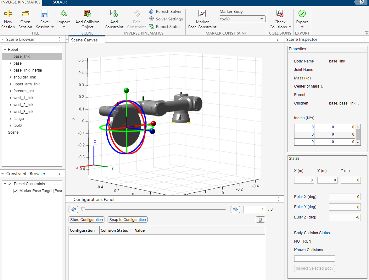

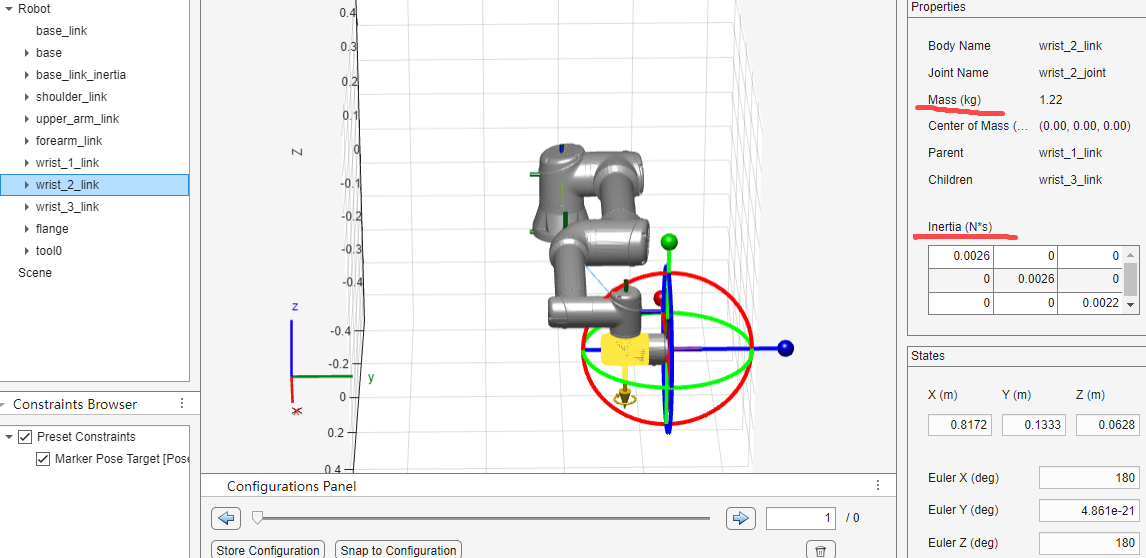
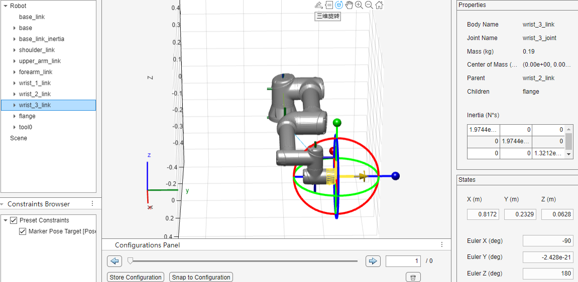
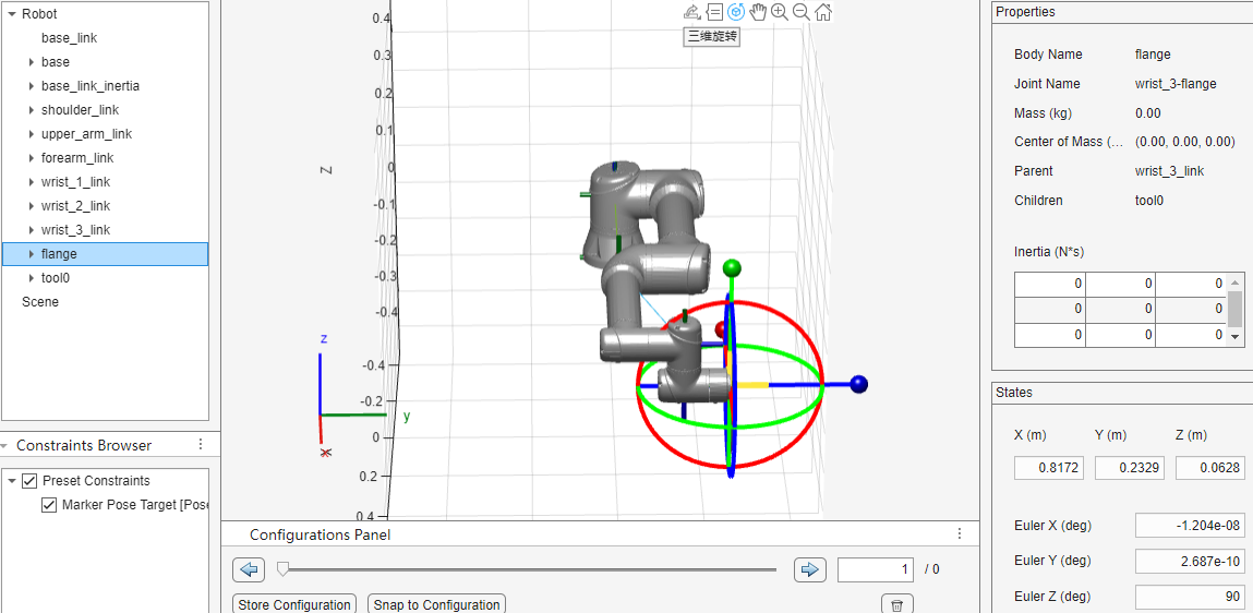
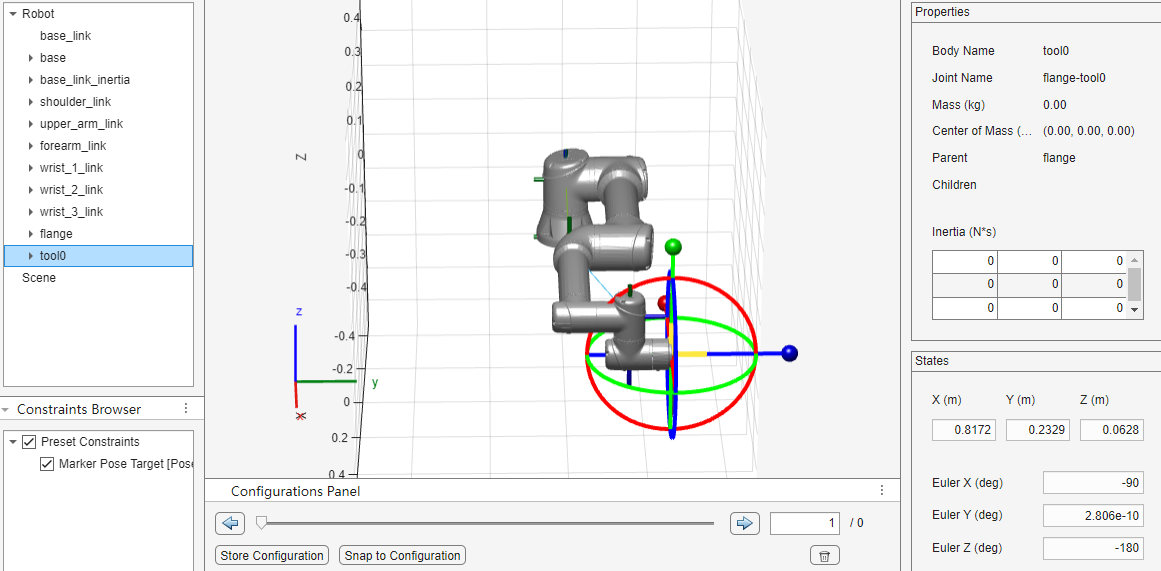
下面是机器人的六个连杆:
- 基座关节(Base Joint)与连杆:
- 通常命名为“基座”或“Base Link”,它是机器人的起点,支撑着整个机械臂结构。
- 肩部关节(Shoulder Joint)与连杆:
- 肩部关节允许机器人手臂在水平面内进行旋转。
- 对应的连杆可以称为“肩部连杆”或“Shoulder Link”,它连接着基座和肘部关节。
- 肘部关节(Elbow Joint)与连杆:
- 肘部关节使机器人手臂能够在垂直平面内弯曲或伸展。
- 对应的连杆称为“肘部连杆”或“Elbow Link”,它连接着肩部连杆和腕部关节。
- 腕部关节(Wrist Joints)与连杆:
- UR5e机器人的腕部通常包含三个关节,分别负责俯仰(Pitch)、偏转(Yaw)和滚动(Roll)运动。
- 这三个关节对应的连杆可以分别命名为“俯仰连杆”、“偏转连杆”和“滚动连杆”,或者简化为“Wrist Pitch Link”、“Wrist Yaw Link”和“Wrist Roll Link”。这些连杆连接着手臂末端和手部执行器。
- 手部执行器(Hand/End Effector):
- 虽然手部执行器本身不是一个关节或连杆,但它是机器人手臂的末端部分,用于执行抓取、操作等任务。

————————————————————————————————
——————————————————————————————————

加载模型后,可以使用MATLAB的机器人工具箱(Robotics Toolbox)进行进一步的分析和仿真。
二、机器人运动学
机器人运动学是研究机器人各部分之间的相对运动、速度和加速度的学科。它分为正向运动学和逆向运动学两部分。
- 正向运动学:给定机器人各关节的变量(如关节角度或位移),计算机器人末端执行器(如机械臂的末端)的位置和姿态。正向运动学的解通常是唯一且容易获得的。
- 逆向运动学:已知机器人末端执行器的期望位置和姿态,求解对应的关节变量。逆向运动学问题往往有多个解,且求解过程更为复杂。
在MATLAB中,可以使用机器人工具箱中的函数(如fkine和ikine)进行正向和逆向运动学分析。
三、动力学仿真分析
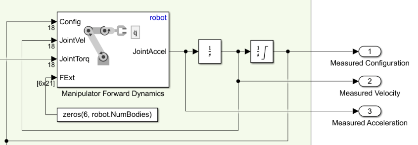
动力学仿真分析是评估机器人系统动力学响应、优化设计参数和提高运动精度和效率的关键步骤。它涉及到对机器人系统力学特性的建模和仿真,包括质量、惯性、运动学关系和外部施加力等。
在MATLAB中,可以使用Simulink和MATLAB/Simulink Robotics System Toolbox进行动力学仿真分析。这些工具提供了丰富的库函数和工具箱,可用于机器人运动学和动力学建模、仿真和控制。
仿真分析的步骤通常包括:
- 建立机器人的动力学模型:根据机器人的结构和任务要求,选择合适的动力学模型,并使用数学方程进行建模。
- 确定仿真参数:设置仿真的时间步长、仿真时长、初始条件等参数,以及机器人的质量、惯性、关节摩擦等参数。
- 进行仿真运行:根据建立的动力学模型和设定的仿真参数,进行仿真运行。仿真运行可以得到机器人系统在不同时刻的位姿、速度、加速度等信息。
- 分析仿真结果:对仿真结果进行分析,评估机器人的动力学性能,如稳定性、精度和效率等。
Model and Control a Manipulator Arm with Robotics and Simscape- MATLAB & Simulink- MathWorks 中国Execute a pick-and-place workflow using an ABB YuMi robot, which demonstrates how to design robot algorithms in Simulink®, and then simulate the action in a test environment using Simscape™.![]() https://ww2.mathworks.cn/help/robotics/ug/model-and-control-a-manipulator-arm-with-simscape.html
https://ww2.mathworks.cn/help/robotics/ug/model-and-control-a-manipulator-arm-with-simscape.html
2-D Path Tracing with Inverse Kinematics- MATLAB & Simulink- MathWorks 中国Calculate inverse kinematics for a simple 2-D manipulator.![]() https://ww2.mathworks.cn/help/robotics/ug/2d-inverse-kinematics-example.html
https://ww2.mathworks.cn/help/robotics/ug/2d-inverse-kinematics-example.html
Perform Trajectory Tracking and Compute Joint Torque for Manipulator Using Simscape- MATLAB & Simulink- MathWorks 中国This example shows you how to use Simulink® with Robotics System Toolbox™ to perform trajectory tracking and compute joint torque required to drive the Simscape™ Multibody™ model of the manipulator along the given joint trajectory.![]() https://ww2.mathworks.cn/help/robotics/ug/perform-trajectory-tracking-and-compute-joint-torque-for-manipulator-using-simscape.html
https://ww2.mathworks.cn/help/robotics/ug/perform-trajectory-tracking-and-compute-joint-torque-for-manipulator-using-simscape.html
Motion Planning and RigidBodyTree Simulation of UR5e for Bin Picking Using manipulatorRRT Algorithm- MATLAB & Simulink- MathWorks 中国This example shows the motion planning algorithm design workflow for a real-world cobot bin picking application.![]() https://ww2.mathworks.cn/help/robotics/urseries/ug/motion-planning-rbt-ur5e-simulation-manipulatorrrt-example.html
https://ww2.mathworks.cn/help/robotics/urseries/ug/motion-planning-rbt-ur5e-simulation-manipulatorrrt-example.html
uniUR5e = loadrobot("universalUR5e");Design inverse kinematics solvers, configurations, and waypoints - MATLAB- MathWorks 中国The Inverse Kinematics Designer enables you to design an inverse kinematics solver for a URDF robot model.![]() https://ww2.mathworks.cn/help/robotics/ref/inversekinematicsdesigner-app.html
https://ww2.mathworks.cn/help/robotics/ref/inversekinematicsdesigner-app.html

