大家好!欢迎来到本次的总结性的一篇文章,因为咸鱼哥这几个月是真的有点小忙(参加了点小比赛,准备考试等等)所以,在数字图像学习后,我来写一个总结性的文章,同时帮助大家学习,相关细节的东西我会后续写对应内容的详解,写文章的时间有点靠后,所以更新有点慢,多说无益,所以那我们开始吧!
注:咸鱼哥这里的学习是根据(数字图像处理 冈萨雷斯 第四版)来进行的,其实学习中用那本书都可以,笔者也看过其他的基本常见教材,内容基本一致。
一、生成灰度图像
% 读取图像
A = imread('1.1.png');
B = imread('1.1.png');
% 显示原始图像
%figure,imshow(A),title('Original Image A');% 提取图像的红色、绿色和蓝色通道
Fxy_r = A(:, :, 1); % 红色通道
Fxy_g = A(:, :, 2); % 绿色通道
Fxy_b = A(:, :, 3); % 蓝色通道(注意这里修正了原代码中的语法错误)% 显示红色、绿色和蓝色通道
% figure;
% subplot(1, 3, 1), imshow(Fxy_r), title('Red Channel');
% subplot(1, 3, 2), imshow(Fxy_g), title('Green Channel');
% subplot(1, 3, 3), imshow(Fxy_b), title('Blue Channel');% 将图像转换为灰度图
A_gray = rgb2gray(A);
B_gray = rgb2gray(B);% 显示灰度图像
%figure,imshow(A_gray),title('Grayscale Image');
这里基本上在数字图像处理中都会用到转到灰度这一块,所以要记得灰度在数字图像处理这一节中的重要性(这里难度不是很大的)。
二、建立图像的坐标系
[Rw, Cl] = size(A_gray);  % 获取灰度图像的尺寸
[X, Y] = meshgrid(1:Cl, 1:Rw);% 生成网格坐标矩阵
Z = double(A_gray);
% figure, surf(X, Y, Z), shading interp, title('3D');
这里的理解可以简单的论述为:一张图片是由很多的像素点构成的,那么,我们要处理图片局部或者分割图片的操作时,就要先知道区域的位置,而这里的操作也是一样。
三、Sobel边缘检测
预操作(注意其中的double类型):
% 6) Sobel边缘检测
imgGrayDouble = double(rgb2gray(A)); % 将RGB图像转换为灰度图像,并转换为double类型
注意:double类型的灰度,在数值上很精确,在相关处理上效果是较好,在后续的增强明暗对比度的二值化时同样适用,但是用double类型一定要注意数值维度相符合,否则程序会报错
1)使用自定义的算子蒙板,进行垂直边缘的检测
% 垂直Sobel边缘检测
%sobelVertical = imfilter(imgGrayDouble, [-1 0 1; -2 0 2; -1 0 1], 'replicate'); % 应用垂直Sobel滤波器
2)使用自定义的算子蒙板,进行水平边缘的检测
% 水平Sobel边缘检测
%sobelHorizontal = imfilter(imgGrayDouble, [-1 -2 -1; 0 0 0; 1 2 1], 'replicate'); % 应用水平Sobel滤波器
这里推荐下面的方式来进行边缘检测(用matlab内置函数进行):
%sobel边缘检测
edges1 = edge(A_gray,'Sobel');%canny边缘检测
edges2 = edge(A_gray,'Canny');
但是注意一点的是,在函数中的参数一为灰度图像。
这里是显示图像的操作,uu们可以跳过相关显示的代码,因为在这里只需要知道imshow、figure、title函数的作用和效果就行,用法简单,所以简单描述一下。
% 显示原始灰度图和边缘检测结果
% figure,imshow(uint8(abs(sobelVertical)), []), title('垂直Sobel边缘检测'); % 显示垂直边缘检测结果
% figure,imshow(uint8(abs(sobelHorizontal)), []), title('水平Sobel边缘检测'); % 显示水平边缘检测结果
% figure,imshow(imgGrayDouble, []), title('原始灰度图像'); % 可选:显示原始灰度图像
% figure,imshow(edges1),title('sobel');
% figure,imshow(edges2),title('canny');
四、计算灰度图像
%计算图像直方图
[m,n] = imhist(A);
%计算CDF值
cdf_A = cumsum(m)/numel(A);
%计算CDF增强图
cdf_ip = (1:length(I)/length(m));% figure,imshow(I),title('gray _ histeq');
%(error)figure,imshow(I1),title('hist');
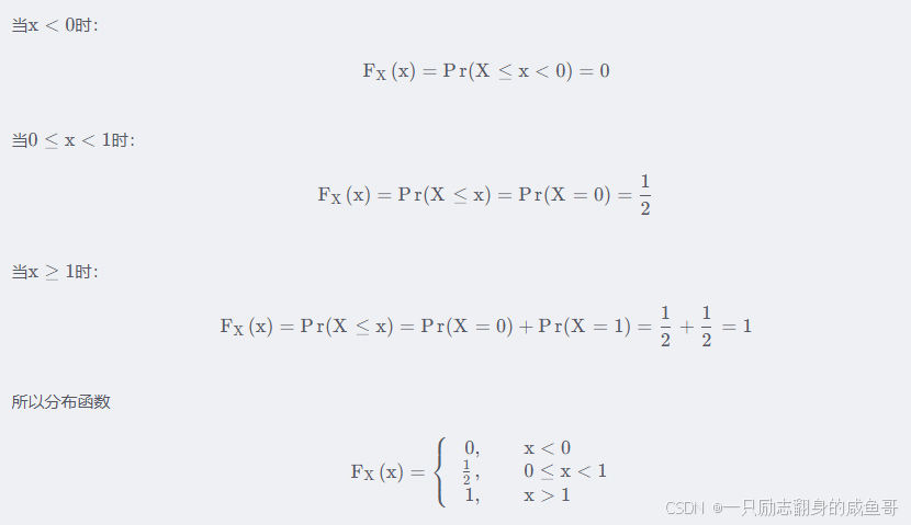
其CDF是分段 ![]() 函数,一般为分段函数比如举例中的掷硬币随机变量,求它的CDF:
函数,一般为分段函数比如举例中的掷硬币随机变量,求它的CDF:

相关理论概念我会在其他的章节内容中讲述,在这里只需要知道CDF是什么东西即可。
实验四,直方图部分代码分析A_color = imread('1.jfif'); % 读取彩色图像
A_eq_gray = my_color_to_gray_histeq(A_color); % 转换为灰度图像并进行直方图均衡化  % 显示结果
figure;
subplot(1, 2, 1), imshow(rgb2gray(A_color)), title('转换后的灰度原图'); % 显示转换后的灰度图像作为对比
subplot(1, 2, 2), imshow(A_eq_gray), title('均衡化后的灰度图像');
function A_eq_gray = my_color_to_gray_histeq(A_color)  % 将彩色图像转换为灰度图像  A_gray = rgb2gray(A_color);  % 获取灰度图像的尺寸  [rows, cols] = size(A_gray);  % 计算灰度图像的直方图  [counts, binLocations] = imhist(A_gray);  % 计算累积分布函数(CDF)  cdf = cumsum(counts) / (rows * cols); % 归一化到[0, 1]范围  % 创建一个查找表(LUT),将原始灰度级映射到新的灰度级  % 注意:MATLAB的索引从1开始,但灰度级从0开始,需要相应调整  lut = zeros(1, 256); % 初始化查找表  for i = 0:255  % 由于CDF是单调递增的,找到第一个大于或等于当前灰度级/255的值所对应的索引  % 使用find的第一个输出,并处理边界情况(即当所有值都小于当前灰度级/255时)  idx = find(cdf >= i/255, 1, 'first');  if isempty(idx)  % 如果找不到,则映射到最大值255(索引256,但减1得到灰度级255)  lut(i+1) = 255;  else  % 否则,映射到对应的灰度级  lut(i+1) = idx - 1; % -1是因为lut的索引从1开始,而灰度级从0开始  end  end  % 应用查找表来均衡化灰度图像  % 注意:这里使用uint8转换来确保输出是8位灰度图像  A_eq_gray = uint8(lut(double(A_gray) + 1)); % +1是因为A_gray的灰度级是从0开始的
end  % 使用示例
五、高斯平滑处理
sigma = 0.1
img_guassion = imgaussfilt(A,sigma);
% figure,imshow(img_guassion),title('guassion_smooth');
六、改变图像大小
img_resize = imresize(A,[64 64]);
% figure,imshow(img_resize);
七、为图像添加不同噪声
D=0.05;
img_noise = imnoise(A_gray,'gaussian',0,0.1);
img_noise1 = imnoise(A_gray,'salt & pepper',D);
img_noise2 = imnoise(A_gray,'poisson' );
% figure,subplot(3,2,1),imshow(img_noise);
% subplot(3,2,2),imshow(img_noise1);
% subplot(3,2,3),imshow(img_noise2);
注:这里是单独的调用函数,实际的学习中个人建议还是学习一下底层的关系。
八、进行图像的滤波处理
1)均值滤波
I_avr = filter2(fspecial('average', [3 3]), double(img_noise));2)加权均值滤波
I_add = filter2(fspecial('gaussian', [3 3], 0.5), double(img_noise));
h_1=[0.1,0.2,0.1;0.2 0.4 0.2;0.1 0.2 0.1];%创建加权滤波模板
I_add2 = imfilter(A,h_1,'same');
% figure;
% imshow(I_add2);
3)中值滤波
I_mid = medfilt2(double(img_noise), [3 3]);4)最大值滤波
I_max = ordfilt2(double(img_noise), 9, ones(3, 3));5)最小值滤波
I_min = ordfilt2(double(img_noise), 1, ones(3, 3));这里是显示出滤波之后的效果图的,和第三部分生成窗口作用一样
% figure;
% subplot(3,2,1),imshow(I_avr);
% subplot(3,2,2),imshow(I_add);
% subplot(3,2,3),imshow(I_max);
% subplot(3,2,4),imshow(I_min);
九、确保A和B具有相同的尺寸
if size(A) ~= size(B)% 选择一个图像作为参考尺寸,这里以B为例A_resized = imresize(A, size(B));
elseA_resized = A;
end
%裁剪图像
A_cropped = A(1:size(B,1), 1:size(B,2));
十、图像二值化
brinary_img = imbinarize(A_resized);十一、相关基本操作
brinary_img = imbinarize(A_cropped);%裁剪完成的二值化操作
brinary_img2= imbinarize(B);%自适应阈值
brinary_img_1 = imbinarize(A, 'adaptive');
brinary_img_2 = imbinarize(B, 'adaptive');%求补集
cpl_img = imcomplement(brinary_img);
%求并集
union_img = brinary_img | brinary_img2;
union_img2 = brinary_img_1| brinary_img_2;%自适应的阈值操作
%
% figure,imshow(cpl_img);
%(error)subplot(1,3,2),imshow(union_img);%图像反转、对数变换、幂次变换和二值化
I_1=255-A_gray;a=1;
I_2=a*log(1+double(A_gray));b=0.5;
I_3=a*(double(A_gray) .^b);%b<1,图像变亮,b>1,图像变暗
I_3=unit8(I_3);
% 二值化
k = 2; % 阈值倍数
I_4 = double(A_gray > mean(A_gray) * k);% figure,subplot(2,2,1),imshow(I_1);
% subplot(2,2,2),imshow(I_2);
% subplot(2,2,3),imshow(I_3);
% subplot(2,2,4),imshow(I_4);
十二、维纳滤波(Wiener Filter)
LEN = 25;
THETA = 20;
PSF = fspecial('motion', LEN, THETA);
J = imfilter(A_gray, PSF, 'conv', 'circular');
NSR = 0;
K = deconvwnr(J, PSF, NSR);
% figure;
% subplot(131); imshow(I);
% subplot(132); imshow(J);
% subplot(133); imshow(K);
十三、锐化
1)(函数)使用 imsharpen 函数进行锐化
sharpened_img = imsharpen(B);% 显示原始图像和锐化后的图像
% figure;
% subplot(1,2,1), imshow(B), title('原始图像');
% subplot(1,2,2), imshow(sharpened_img), title('锐化后的图像');
2)锐化(laplacian)拉普拉斯滤波器
% 定义拉普拉斯滤波器
laplacian_filter = [0 -1 0; -1 4 -1; 0 -1 0];% 应用拉普拉斯滤波器
laplacian_img = filter2(laplacian_filter, double(B_gray), 'same');% 将拉普拉斯结果加回到原始图像以锐化
sharpened_img = B_gray + uint8(laplacian_img);% 显示原始图像和锐化后的图像
% figure;
% subplot(1,2,1), imshow(B), title('原始图像');
% subplot(1,2,2), imshow(sharpened_img), title('锐化后的图像');
十四、使用高斯混合模型(GMM)进行图像分割
B = im2double(B);% 将图像转换为双精度型,以便进行计算
% 使用高斯混合模型进行图像分割
num_clusters = 2;
gmm_model = fitgmdist(double(B_gray(:)), num_clusters);% 预测每个像素的类别
pixel_labels = cluster(gmm_model, double(B_gray(:)));
pixel_labels = reshape(pixel_labels,size(B_gray));% 提取前景区域和背景区域
foreground =pixel_labels == 1;
background =pixel_labels == 2;
% 计算前景区域的距离变换
distance_transform = bwdist(~foreground);
% 计算前景边缘
edges = edge(distance_transform, 'Canny');
%显示结果figure
% subplot(235)imshow(distance_transform);
% title('距离变换结果');
colormap(jet);
colorbar;
subplot(2,3,[1:2]) imshow(B);
title('原始图像')subplot(233)imshow(foreground)title('前景图')subplot(234)
imshow(background)
title('背景图')subplot(236)imshow(edges); % 显示边缘图title('前景边缘显示结果');
十五、滤波器函数的设定
预处理:
[ra,ca] = size(A_gray);
P = 2 * ra,Q =2 * ca;%设置填充后的图像大小
A_2 = zeros(P,Q);%用零填充图像;
A_2(1:ra,1:ca)=A_gray;
[Ra,Ca]=size(A_2);
[y,x]=meshgrid(0:Ca-1,0:Ra-1);%建立空域二维坐标系
F_B=fft2(A_2.*(-1).^(x+y));%傅里叶变化乘以(-1)^(x+y)
1)理想低通滤波器
D_1=12;
H_1=zeros(P,Q);
for n=1:Pfor m = 1:Qif((n-P/2-1)^2+(m-Q/2-1)^2 <=(D_1)^2);H_1(n,m)=1;%赋值给1elseH_1(n,m)=0;%赋值给0endend
end
figure,mesh(H_1),title('滤波器透视图,理想低通D0=10');
G=F_B.*H_1;
fa=ifft2(G);
fa=real(fa).*(-1).^(x+y);
fA=fa(1:ra,1:ca);%去除补零的部分;
figure,subplot(1,3,2),imshow(fA,[]);
2)理想高通滤波器
figure
subplot(4,2,1),imshow(A),title('原图');
H_2= 1-H_1;
subplot(4,2,3),mesh(H_2),title('滤波器透视图,理想高通D0=10');
G1=F_B.*H_2;
fa1=ifft2(G1);
fa1=real(fa1).*(-1).^(x+y);
fA1=fa1(1:ra,1:ca);
subplot(1,3,3),imshow(fA1,[]);
3)高斯低通滤波器
figure
subplot(4,2,1),imshow(A),title('原图');
U = 0:P-1;
V = 0:Q-1;%赋值傅里叶频谱频率值
[V,U] = meshgrid(0:Q-1,0:P-1);%生成频域二维坐标
D_mid = sqrt((U-P/2).^2+(V-Q/2).^2);%赋值频域点到中心距离
H_uv = exp(-D_mid.^2/2/D_0/D_0);%生成滤波器
subplot(4,2,3),mesh(H_uv),title('滤波器透视图,高斯低D0=10)');
G_pxy=F_B.*H_uv;%用滤波器滤波
g_pxy=ifft2(G_pxy);%做逆傅里叶变换
g_pxy=real(g_pxy).*(-1).^(x+y);%取实部后乘以(-1)的x+y次方
g_xy=g_pxy(1:ra,1:ca);%除去补零部分
subplot(4,2,4),imshow(g_xy,[]),title('滤波结果图,高斯低D0=10)');
4)高斯高通滤波器
figure
subplot(4,2,1),imshow(A),title('原图');
H_uv_3=1-H_uv;%用1减去低通滤波器得到高通滤波器
subplot(4,2,3),mesh(H_uv_3),title('滤波器透视图,高斯高0=10)');
G_pxy_3=F_B.*H_uv_3;%用滤波器滤波
g_pxy_3=ifft2(G_pxy_3);%做逆傅里叶变换
g_pxy_3=real(g_pxy_3).*(-1).^(x+y);%取实部后乘以(-1)的x+y次方
g_xy_3=g_pxy_3(1:ra,1:ca);%除去补零部分
subplot(4,2,4),imshow(g_xy_3,[]),title('滤波结果图,高斯高D0=10)');
5)巴特沃斯低通滤波器
U=0:P-1;V=0:Q-1;%赋值傅里叶频谱频率值
[V,U]=meshgrid(0:Q-1,0:P-1);%生成频域二维坐标
D_mid=sqrt((U-P/2).^2+(V-Q/2).^2);%赋值频域点到中心距离figure;
subplot(4,2,1),imshow(A),title('原图');D_3=20;%赋值截止频率
n=1;%赋值巴特沃斯滤波器阶数
H_UV=1./(1+(D_mid/D_3).^(2*n));%生成滤波器
subplot(4,2,3),mesh(H_UV),title('滤波器透视图,巴低通D0=20,n=1)');
G_PXY=F_B.*H_UV;%用滤波器滤波
f_PXY=ifft2(G_PXY);%做逆傅里叶变换
f_PXY=real(f_PXY).*(-1).^(x+y);%取实部后乘以(-1)的x+y次方
f_XY=f_PXY(1:ra,1:ca);%除去补零部分
subplot(4,2,4),imshow(f_XY,[]),title('滤波结果图,巴低通D0=20,n=1)');
6)巴特沃斯高通滤波器
figure
subplot(4,2,1),imshow(A),title('原图');
n=1;%赋值巴特沃斯滤波器阶数
H_UV=1./(1+(D_3./D_mid).^(2*n));%生成滤波器
subplot(4,2,3),mesh(H_UV),title('滤波器透视图,巴高通D0=20,n=1)');
G_PXY=F_B.*H_UV;%用滤波器滤波
f_PXY=ifft2(G_PXY);%做逆傅里叶变换
f_PXY=real(f_PXY).*(-1).^(x+y);%取实部后乘以(-1)的x+y次方
f_XY=f_PXY(1:ra,1:ca);%除去补零部分
subplot(4,2,4),imshow(f_XY,[]),title('滤波结果图,巴高通D0=20,n=1)');
此外还有陷波滤波器等
其中陷波滤波器、巴特沃斯滤波器、高斯滤波器的差异都很小,只是在于滤波器使用的公式不一样,所以我们在学习的时候可以举一反三的学习,这也是学习的一种良好的方式。
十六、形态学相关操作
1)腐蚀图像
se1=[1;1;1]; %线型结构元素
FuShi=imerode(BianYuan,se1);
2)图像聚类、填充图像
se2=strel('rectangle',[25,25]); %矩形结构元素
TianChong=imclose(FuShi,se2);%图像聚类、填充图像
3)移除指定面积图像
YuanShiLvBo=bwareaopen(TianChong,2000);%从对象中移除面积小于2000的小对象
十七、RGB to HSI
rgbImage = imread('image.jpg');rgbImage = im2double(rgbImage); % Normalize to [0,1]%Separate color channelsR=rgbImage(:,:,1);G=rgbImage(:,:,2);B=rgbImage(:,:,3);%Calculate intensityI = (R +G+B)/3;%Calculate saturationminRGB =min(min(R, G), B);S =1-(minRGB ./ I);S(I == 0) = 0; % Handle division by zero%Calculate huetheta = acos(0.5 * ((R- G) + (R- B)) ./ sqrt((R- G).^2 + (R- B).*(G- B)));H=theta;H(B >G) =2*pi- H;%Normalize H to [0,1]H=H/(2*pi);%Combine channels into HSI imagehsiImage = cat(3, H, S, I);%Display the resultimshow(hsiImage);title('HSI Image')
十八、RGB to HSV
%Read the imagergbImage = imread('image.jpg');%Convert to HSVhsvImage = rgb2hsv(rgbImage);%Display the resultimshow(hsvImage);title('HSV Image');%Assuming `hsiImage` is the HSI image you already have%Extract individual channelsH=hsiImage(:,:,1); % HueS =hsiImage(:,:,2); % SaturationI = hsiImage(:,:,3); % Intensity%Display the individual componentsfigure;subplot(1, 3, 1);imshow(H);title('Hue');subplot(1, 3, 2);imshow(S);title('Saturation');subplot(1, 3, 3);imshow(I);title('Intensity')十九、彩图的单色图片展示
% 确保图像是RGB格式
if size(img, 3) == 3% 创建单色图像redImg = img;greenImg = img;blueImg = img;% 将其他颜色通道设置为0redImg(:,:,2:3) = 0; % 红色通道图像,G和B通道为0greenImg(:,:,3:3) = 0; % 绿色通道图像,R和B通道为0blueImg(:,:,1:2) = 0; % 蓝色通道图像,R和G通道为0% 显示单色图像figure;subplot(1,3,1);imshow(redImg);title('Red Channel Image');subplot(1,3,2);imshow(greenImg);title('Green Channel Image');subplot(1,3,3);imshow(blueImg);title('Blue Channel Image');
elsedisp('The image is not in RGB format.');
end
二十、绘制区域图像
p=ones(256,256);
p(96:105,:)=0;
p(:,96:105)=0;
figure;
subplot(1,3,1),imshow(p);
p2=ones(256,256);
p2(96:105,:)=0;
p2(:,96:105)=0;
subplot(1,3,2),imshow(p2);
j=union(p,p2);
subplot(1,3,3),imshow(j);
好了,到这里,我们的matlab版对于数字图像处理课程学习的总结就结束了,我们可以发现基本上的所有操作都需要灰度的处理(除需要彩色图像时候,我们采用分图层或者显示同色图像),其他的过程中会有底层编写或者函数的调用,这里咸鱼哥建议大家有时间的话也可以使用matlab工具箱(2022版以上的都有)来进行其他好玩的操作,比如:无人机算法路径规划实现,算法验证等,其实咸鱼哥个人感觉还是很有意思的。
关于理论的分析,咸鱼哥会在后续一个个总结写出,相当于一种总结和学习的经历,望诸君共勉,我们共同学习!
uu们!我们下次见!
另记:以上代码均测试过,可以在matlab中运行,所以初学者也可以放心学习,如有不会之处可以在评论区发表,我会认真解答的。(此外,以上代码结果均太多,而且大部分相同,所以希望大家抽时间在matlab中运行,这样起到学习和理解,也方便我们看清数字图像处理技术有什么作用)。


