前言
这个例子介绍了 Revit 中的一个实体几何裁剪。
内容
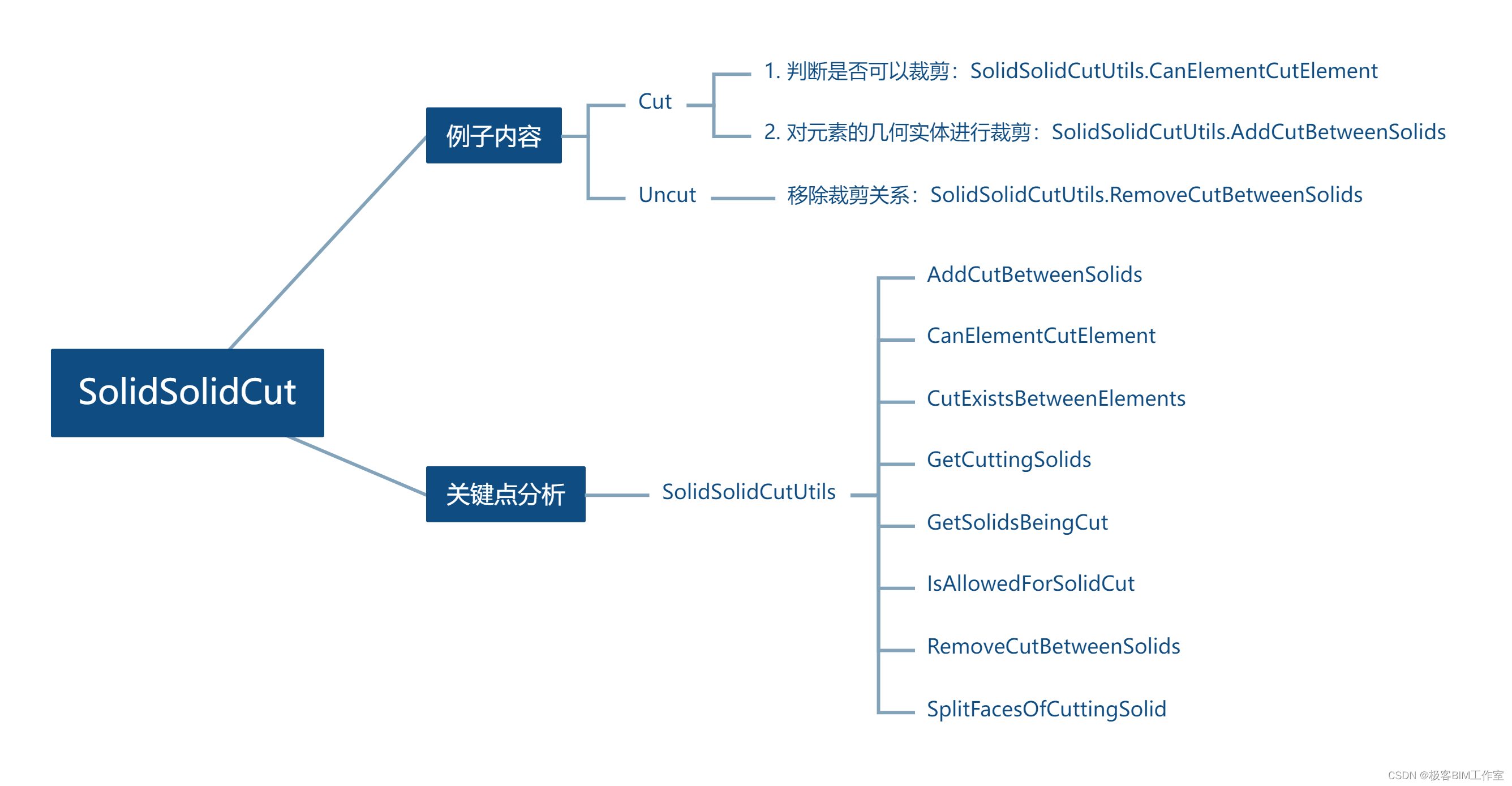
这个例子介绍如何使用 SolidSolidCutUtils 的接口来做几何裁剪以及取消几何裁剪。内容相对来说非常简单。
namespace Autodesk.Revit.DB
{public static class SolidSolidCutUtils{public static void AddCutBetweenSolids(Document document, Element solidToBeCut, Element cuttingSolid, bool splitFacesOfCuttingSolid);public static void AddCutBetweenSolids(Document document, Element solidToBeCut, Element cuttingSolid);public static bool CanElementCutElement(Element cuttingElement, Element cutElement, out CutFailureReason reason);public static bool CutExistsBetweenElements(Element first, Element second, out bool firstCutsSecond);public static ICollection<ElementId> GetCuttingSolids(Element element);public static ICollection<ElementId> GetSolidsBeingCut(Element element);public static bool IsAllowedForSolidCut(Element element);public static bool IsElementFromAppropriateContext(Element element);public static void RemoveCutBetweenSolids(Document document, Element first, Element second);public static void SplitFacesOfCuttingSolid(Element first, Element second, bool split);}
}
效果展示:
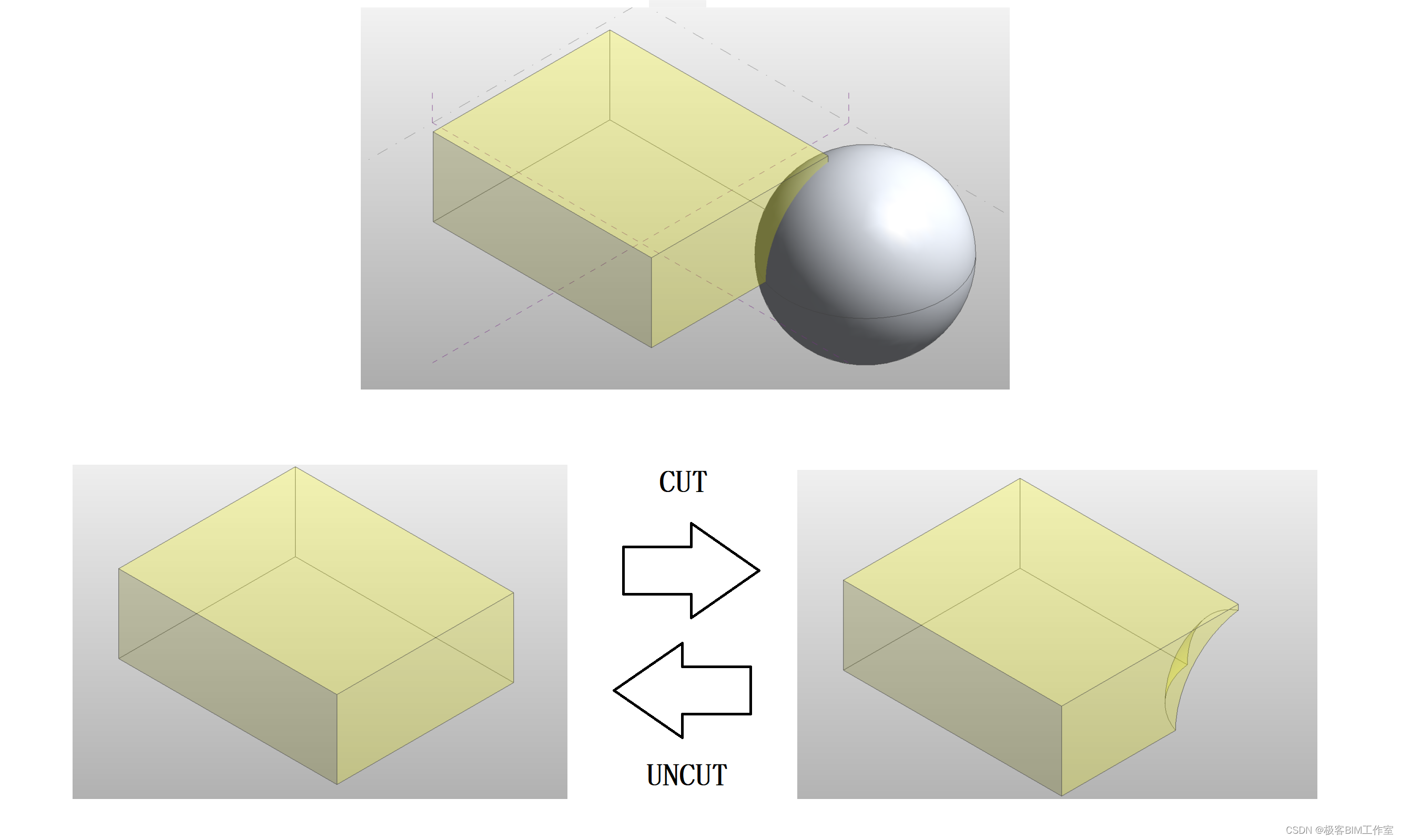
Cut 命令的核心逻辑
// 获取要操作的元素
Element solidToBeCut = activeDoc.GetElement(new ElementId(solidToBeCutElementId));
Element cuttingSolid = activeDoc.GetElement(new ElementId(cuttingSolidElementId));
// 判断能否进行裁剪
CutFailureReason cutFailureReason = new CutFailureReason();
if (SolidSolidCutUtils.CanElementCutElement(cuttingSolid, solidToBeCut, out cutFailureReason)){// 进行裁剪的操作SolidSolidCutUtils.AddCutBetweenSolids(activeDoc, solidToBeCut, cuttingSolid);
}
UnCut 命令的核心逻辑
// 获取要操作的元素
Element solidToBeCut = activeDoc.GetElement(new ElementId(solidToBeCutElementId));
Element cuttingSolid = activeDoc.GetElement(new ElementId(cuttingSolidElementId));
// 取消裁剪关系
SolidSolidCutUtils.RemoveCutBetweenSolids(activeDoc, solidToBeCut, cuttingSolid);
参考
Revit API 几何专题 5: 体 - Solid


