实验6 VLAN划分....................................................................... - 30 -
实验7 路由器调试及常用命令使用........................................ - 42 -
实验8 配置静态路由器............................................................ - 54 -
实验9 路由器RIP协议配置.................................................... - 74 -
实验10 路由器OSPF协议配置................................................ - 85 -
实验6 VLAN划分
一、实验目的与要求:
- 掌握VLAN 的基本配置
- 掌握ACCESS接口配置方法
- 掌握trunk接口配置方法
- 掌握ACCESSt和trunk接口加入相应VLAN的方法
二、实验内容:
1、掌握VLAN 的基本配置。
2、掌握ACCESS接口配置方法
3、掌握trunk接口配置方法
三、实验器材:
计算机+华为模拟器+交换机(华为)
四、实验步骤:
- ACCESS接口配置方法
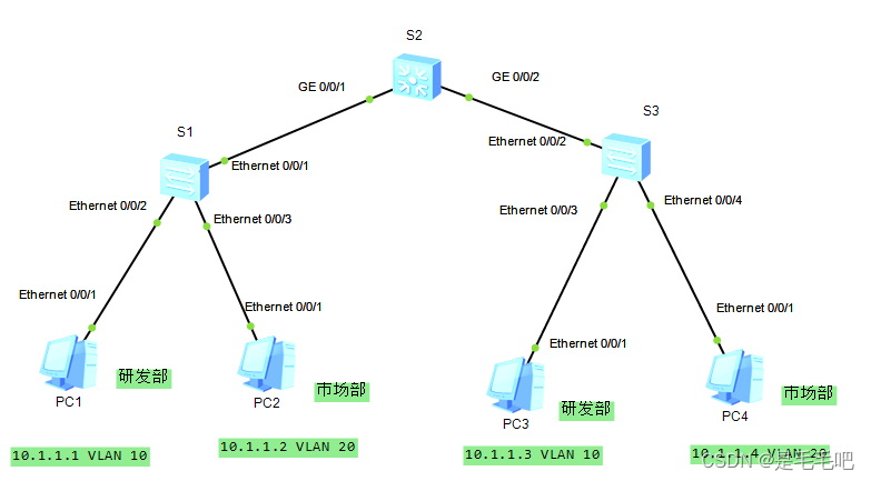
(1)实验拓扑

(2)实验IP
| 设备 | 接口 | IP 地址 | 子网掩码 | 默认网关 |
| PC1 | Ethernet0/0/1 | 10.1.1.1 | 255.255.255.0 | N/A |
| PC2 | Ethernet0/0/1 | 10.1.1.2 | 255.255.255.0 | N/A |
| PC3 | Ethernet0/0/1 | 10.1.1.3 | 255.255.255.0 | N/A |
| PC4 | Ethernet0/0/1 | 10.1.1.4 | 255.255.255.0 | N/A |
| PC5 | Ethernet0/0/1 | 10.1.1.5 | 255.255.255.0 | N/A |
- 基本配置
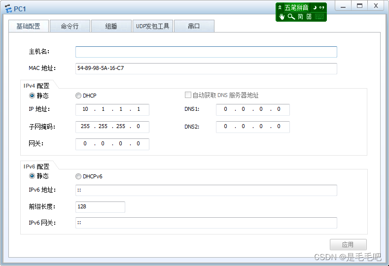
PC1到PC5 主机设置IP地址。如下

<Huawei>sys
Enter system view, return user view with Ctrl+Z.
[Huawei]sysname S1
[S1]
配置两台交换机
<Huawei>sys
Enter system view, return user view with Ctrl+Z.
[Huawei]sysname S2
[S2]
- 创建VLAN
在S1上使用两条命令分别创建VLAN10和VLAN 20
[S1]vlan 10
[S1-vlan10]
Dec 7 2017 21:31:15-08:00 S1 DS/4/DATASYNC_CFGCHANGE:OID 1.3.6.1.4.1.2011.5.25.
191.3.1 configurations have been changed. The current change number is 5, the change loop count is 0, and the maximum number of records is 4095.
[S1-vlan10]vlan 20
[S1-vlan20]
Dec 7 2017 21:31:45-08:00 S1 DS/4/DATASYNC_CFGCHANGE:OID 1.3.6.1.4.1.2011.5.25.
191.3.1 configurations have been changed. The current change number is 6, the ch
ange loop count is 0, and the maximum number of records is 4095.
在S1上使用一条VLAN BATCH创建VLAN30和VLAN 40
[S2]vlan batch 30 40
Info: This operation may take a few seconds. Please wait for a moment...done.
[S2]
Dec 7 2017 21:38:16-08:00 S2 DS/4/DATASYNC_CFGCHANGE:OID 1.3.6.1.4.1.2011.5.25.
191.3.1 configurations have been changed. The current change number is 5, the change loop count is 0, and the maximum number of records is 4095.
使用display vlan 命令查看VLAN 的相关信息
[S1]display vlan
The total number of vlans is : 3
U: Up; D: Down; TG: Tagged; UT: Untagged;
MP: Vlan-mapping; ST: Vlan-stacking;
#: ProtocolTransparent-vlan; *: Management-vlan;
VID Type Ports
1 common UT:Eth0/0/1(U) Eth0/0/2(U) Eth0/0/3(U) Eth0/0/4(D)
Eth0/0/5(U) Eth0/0/6(D) Eth0/0/7(D) Eth0/0/8(D)
Eth0/0/9(D) Eth0/0/10(D) Eth0/0/11(D) Eth0/0/12(D)
Eth0/0/13(D) Eth0/0/14(D) Eth0/0/15(D) Eth0/0/16(D)
Eth0/0/17(D) Eth0/0/18(D) Eth0/0/19(D) Eth0/0/20(D)
Eth0/0/21(D) Eth0/0/22(D) GE0/0/1(D) GE0/0/2(D)
10 common
20 common
VID Status Property MAC-LRN Statistics Description
1 enable default enable disable VLAN 0001
10 enable default enable disable VLAN 0010
20 enable default enable disable VLAN 0020
[S1]
[S2]display vlan
The total number of vlans is : 3
U: Up; D: Down; TG: Tagged; UT: Untagged;
MP: Vlan-mapping; ST: Vlan-stacking;
#: ProtocolTransparent-vlan; *: Management-vlan;
VID Type Ports
1 common UT:Eth0/0/1(U) Eth0/0/2(U) Eth0/0/3(D) Eth0/0/4(D)
Eth0/0/5(U) Eth0/0/6(D) Eth0/0/7(D) Eth0/0/8(D)
Eth0/0/9(D) Eth0/0/10(D) Eth0/0/11(D) Eth0/0/12(D)
Eth0/0/13(D) Eth0/0/14(D) Eth0/0/15(D) Eth0/0/16(D)
Eth0/0/17(D) Eth0/0/18(D) Eth0/0/19(D) Eth0/0/20(D)
Eth0/0/21(D) Eth0/0/22(D) GE0/0/1(D) GE0/0/2(D)
30 common
40 common
VID Status Property MAC-LRN Statistics Description
1 enable default enable disable VLAN 0001
30 enable default enable disable VLAN 0030
40 enable default enable disable VLAN 0040
[S2]
- 配置ACCESS 接口
[S1]int eth 0/0/1
[S1-Ethernet0/0/1]port link-type access //定义交换机连接PC 机的ACCESS 接口
[S1-Ethernet0/0/1]port default vlan 10 //接口默认为VLAN 10
[S1-Ethernet0/0/1]int eth 0/0/2
[S1-Ethernet0/0/2]port link-type access //定义交换机连接PC 机的ACCESS 接口
[S1-Ethernet0/0/2]port default vlan 10 //接口默认为VLAN 10
[S1-Ethernet0/0/2]int eth 0/0/3
[S1-Ethernet0/0/3]port link-type access //定义交换机连接PC 机的ACCESS 接口
[S1-Ethernet0/0/3]port default vlan 20 //接口默认为VLAN 20
[S2]int eth 0/0/1
[S2-Ethernet0/0/1]port link-type access //定义交换机连接PC 机的ACCESS 接口
[S2-Ethernet0/0/1]port default vlan 30 //接口默认为VLAN 30
[S2-Ethernet0/0/1]int eth 0/0/2
[S1-Ethernet0/0/2]port link-type access //定义交换机连接PC 机的ACCESS 接口
[S2-Ethernet0/0/2]port default vlan 40 //接口默认为VLAN 40
使用display vlan 命令查看VLAN 的相关信息
[S1]dis vlan
The total number of vlans is : 3
U: Up; D: Down; TG: Tagged; UT: Untagged;
MP: Vlan-mapping; ST: Vlan-stacking;
#: ProtocolTransparent-vlan; *: Management-vlan;
VID Type Ports
1 common UT:Eth0/0/4(D) Eth0/0/5(U) Eth0/0/6(D) Eth0/0/7(D)
Eth0/0/8(D) Eth0/0/9(D) Eth0/0/10(D) Eth0/0/11(D)
Eth0/0/12(D) Eth0/0/13(D) Eth0/0/14(D) Eth0/0/15(D)
Eth0/0/16(D) Eth0/0/17(D) Eth0/0/18(D) Eth0/0/19(D)
Eth0/0/20(D) Eth0/0/21(D) Eth0/0/22(D) GE0/0/1(D)
GE0/0/2(D)
10 common UT:Eth0/0/1(U) Eth0/0/2(U)
20 common UT:Eth0/0/3(U)
VID Status Property MAC-LRN Statistics Description
1 enable default enable disable VLAN 0001
10 enable default enable disable VLAN 0010
20 enable default enable disable VLAN 0020
[S2]dis vlan
The total number of vlans is : 3
U: Up; D: Down; TG: Tagged; UT: Untagged;
MP: Vlan-mapping; ST: Vlan-stacking;
#: ProtocolTransparent-vlan; *: Management-vlan;
VID Type Ports
1 common UT:Eth0/0/3(D) Eth0/0/4(D) Eth0/0/5(U) Eth0/0/6(D)
Eth0/0/7(D) Eth0/0/8(D) Eth0/0/9(D) Eth0/0/10(D)
Eth0/0/11(D) Eth0/0/12(D) Eth0/0/13(D) Eth0/0/14(D)
Eth0/0/15(D) Eth0/0/16(D) Eth0/0/17(D) Eth0/0/18(D)
Eth0/0/19(D) Eth0/0/20(D) Eth0/0/21(D) Eth0/0/22(D)
GE0/0/1(D) GE0/0/2(D)
30 common UT:Eth0/0/1(U)
40 common UT:Eth0/0/2(U)
VID Status Property MAC-LRN Statistics Description
1 enable default enable disable VLAN 0001
30 enable default enable disable VLAN 0030
40 enable default enable disable VLAN 0040
- 检查配置结果
PC>ping 10.1.1.2
Ping 10.1.1.2: 32 data bytes, Press Ctrl_C to break
From 10.1.1.2: bytes=32 seq=1 ttl=128 time=31 ms
From 10.1.1.2: bytes=32 seq=2 ttl=128 time=47 ms
--- 10.1.1.2 ping statistics ---
5 packet(s) transmitted
5 packet(s) received
0.00% packet loss
round-trip min/avg/max = 31/40/47 ms
PC>ping 10.1.1.3
Ping 10.1.1.3: 32 data bytes, Press Ctrl_C to break
From 10.1.1.1: Destination host unreachable
From 10.1.1.1: Destination host unreachable
--- 10.1.1.3 ping statistics ---
5 packet(s) transmitted
0 packet(s) received
100.00% packet loss
- 删除配置文件reset saved-configuration
<S1>reset saved-configuration
Warning: The action will delete the saved configuration in the device.
The configuration will be erased to reconfigure. Continue? [Y/N]:y
Warning: Now clearing the configuration in the device.
Dec 7 2017 22:48:47-08:00 S1 %%01CFM/4/RST_CFG(l)[60]:The user chose Y when dec
iding whether to reset the saved configuration.
Info: Succeeded in clearing the configuration in the device.
<S1>reboot //重启交换机设置
Info: The system is now comparing the configuration, please wait.
Warning: All the configuration will be saved to the configuration file for the n
ext startup:, Continue?[Y/N]:n //不保存配置文件
Info: If want to reboot with saving diagnostic information, input 'N' and then e
xecute 'reboot save diagnostic-information'.
System will reboot! Continue?[Y/N]:y
2、掌握trunk接口配置方法
(1)实验拓扑
(2)实验IP
| 设备 | 接口 | IP 地址 | 子网掩码 | 默认网关 |
| PC1 | Ethernet0/0/1 | 10.1.1.1 | 255.255.255.0 | N/A |
| PC2 | Ethernet0/0/1 | 10.1.1.2 | 255.255.255.0 | N/A |
| PC3 | Ethernet0/0/1 | 10.1.1.3 | 255.255.255.0 | N/A |
| PC4 | Ethernet0/0/1 | 10.1.1.4 | 255.255.255.0 | N/A |
(3)实验步骤
基本配置
PC1到PC5 主机设置IP地址。如下
<Huawei>sys
Enter system view, return user view with Ctrl+Z.
[Huawei]sysname S1
[S1]
配置两台交换机
<Huawei>sys
Enter system view, return user view with Ctrl+Z.
[Huawei]sysname S2
[S2]
<Huawei>sys
Enter system view, return user view with Ctrl+Z.
[Huawei]sysname S3
[S3]
创建VLAN ,配置ACCESS接口
在3台交换机上分别创建VLAN10和VLAN 20,研发部为VLAN10,市场部为VLAN 20
[S1]vlan 10
[S1-vlan10]
Dec 7 2017 21:31:15-08:00 S1 DS/4/DATASYNC_CFGCHANGE:OID 1.3.6.1.4.1.2011.5.25.
191.3.1 configurations have been changed. The current change number is 5, the change loop count is 0, and the maximum number of records is 4095.
[S1-vlan10] description R&D //描述研发部
[S1-vlan10]vlan 20
[S1-vlan20]
Dec 7 2017 21:31:45-08:00 S1 DS/4/DATASYNC_CFGCHANGE:OID 1.3.6.1.4.1.2011.5.25.
191.3.1 configurations have been changed. The current change number is 6, the ch
ange loop count is 0, and the maximum number of records is 4095.
[S1-vlan20]description market //描述市场部
[S2]vlan 10
[S2-vlan10]
Dec 7 2017 21:31:15-08:00 S1 DS/4/DATASYNC_CFGCHANGE:OID 1.3.6.1.4.1.2011.5.25.
191.3.1 configurations have been changed. The current change number is 5, the change loop count is 0, and the maximum number of records is 4095.
[S1-vlan10] description R&D //描述研发部
[S2-vlan10]vlan 20
Dec 7 2017 21:31:45-08:00 S1 DS/4/DATASYNC_CFGCHANGE:OID 1.3.6.1.4.1.2011.5.25.
191.3.1 configurations have been changed. The current change number is 6, the ch
ange loop count is 0, and the maximum number of records is 4095.
[S2-vlan20]description market //描述市场部
[S3]vlan 10
[S3-vlan10]
Dec 7 2017 21:31:15-08:00 S1 DS/4/DATASYNC_CFGCHANGE:OID 1.3.6.1.4.1.2011.5.25.
191.3.1 configurations have been changed. The current change number is 5, the change loop count is 0, and the maximum number of records is 4095.
[S3-vlan10] description R&D //描述研发部
[S3-vlan10]vlan 20
[S3-vlan20]
Dec 7 2017 21:31:45-08:00 S1 DS/4/DATASYNC_CFGCHANGE:OID 1.3.6.1.4.1.2011.5.25.
191.3.1 configurations have been changed. The current change number is 6, the ch
ange loop count is 0, and the maximum number of records is 4095.
[S3-vlan20]description market //描述市场部
使用display vlan 命令查看VLAN 的相关信息
[S3]display vlan
The total number of vlans is : 3
U: Up; D: Down; TG: Tagged; UT: Untagged;
MP: Vlan-mapping; ST: Vlan-stacking;
#: ProtocolTransparent-vlan; *: Management-vlan;
VID Type Ports
1 common UT:Eth0/0/1(U) Eth0/0/2(U) Eth0/0/3(U) Eth0/0/4(D)
Eth0/0/5(D) Eth0/0/6(D) Eth0/0/7(D) Eth0/0/8(D)
Eth0/0/9(D) Eth0/0/10(D) Eth0/0/11(D) Eth0/0/12(D)
Eth0/0/13(D) Eth0/0/14(D) Eth0/0/15(D) Eth0/0/16(D)
Eth0/0/17(D) Eth0/0/18(D) Eth0/0/19(D) Eth0/0/20(D)
Eth0/0/21(D) Eth0/0/22(D) GE0/0/1(D) GE0/0/2(D)
10 common
20 common
VID Status Property MAC-LRN Statistics Description
1 enable default enable disable VLAN 0001
10 enable default enable disable R&D
20 enable default enable disable market
<S3>dis vlan summary //查看所配置VLAN的简要信息
static vlan:
Total 3 static vlan.
1 10 20
dynamic vlan:
Total 0 dynamic vlan.
reserved vlan:
Total 0 reserved vlan.
<S3>
配置ACCESS 接口
[S1]int eth 0/0/2
[S1-Ethernet0/0/2]port link-type access //定义交换机连接PC 机的ACCESS 接口
[S1-Ethernet0/0/2]port default vlan 10 //接口默认为VLAN 10
[S1-Ethernet0/0/2]int eth 0/0/3
[S1-Ethernet0/0/3]port link-type access //定义交换机连接PC 机的ACCESS 接口
[S1-Ethernet0/0/3]port default vlan 20 //接口默认为VLAN 20
[S2]int eth 0/0/3
[S2-Ethernet0/0/3]port link-type access //定义交换机连接PC 机的ACCESS 接口
[S2-Ethernet0/0/3]port default vlan 10 //接口默认为VLAN 10
[S2-Ethernet0/0/3]int eth 0/0/4
[S2-Ethernet0/0/4]port link-type access //定义交换机连接PC 机的ACCESS 接口
[S2-Ethernet0/0/4]port default vlan 20 //接口默认为VLAN 20
使用display port vlan 命令查看VLAN和接口配置 的相关信息
[S1]dis port vlan
Port Link Type PVID Trunk VLAN List
Ethernet0/0/1 hybrid 1 -
Ethernet0/0/2 access 10 -
Ethernet0/0/3 access 20 -
[S2]dis port vlan
Port Link Type PVID Trunk VLAN List
Ethernet0/0/1 hybrid 1 -
Ethernet0/0/2 hybrid 1 -
Ethernet0/0/3 access 10 -
Ethernet0/0/4 access 20 -
配置Trunk接口
测试PC1 与PC3之间的连通性
PC>ping 10.1.1.3
Ping 10.1.1.3: 32 data bytes, Press Ctrl_C to break
From 10.1.1.1: Destination host unreachable
From 10.1.1.1: Destination host unreachable
--- 10.1.1.3 ping statistics ---
5 packet(s) transmitted
0 packet(s) received
100.00% packet loss
测试PC2 与PC4之间的连通性
PC>ping 10.1.1.4
Ping 10.1.1.4: 32 data bytes, Press Ctrl_C to break
From 10.1.1.2: Destination host unreachable
From 10.1.1.2: Destination host unreachable
--- 10.1.1.4 ping statistics ---
5 packet(s) transmitted
0 packet(s) received
100.00% packet loss
配置Trunk 接口
在S1上配置E0/0/1为trunk 接口,允许VLAN10和VLAN 20通过
[S1]int eth 0/0/1
[S1-Ethernet0/0/1]port link-type trunk
Dec 11 2017 14:06:12-08:00 S1 DS/4/DATASYNC_CFGCHANGE:OID 1.3.6.1.4.1.2011.5.25.
191.3.1 configurations have been changed. The current change number is 6, the ch
ange loop count is 0, and the maximum number of records is 4095.psys
Error: Unrecognized command found at '^' position.
[S1-Ethernet0/0/1]port trunk allow-pass vlan 10 20
在S2上配置E0/0/2为trunk 接口,允许VLAN10和VLAN 20通过
[S2]int eth 0/0/2
[S2-Ethernet0/0/2]port link-type trunk
[S2-Ethernet0/0/2]port trunk allow-pass vlan 10 20
在S3上配置GE0/0/1和GE0/0/2为trunk 接口,允许所有VLAN通过
[S3]int g 0/0/1
[S3-GigabitEthernet0/0/1]port link-type trunk
Dec 11 2017 14:29:11-08:00 S3 DS/4/DATASYNC_CFGCHANGE:OID 1.3.6.1.4.1.2011.5.25.
191.3.1 configurations have been changed. The current change number is 5, the ch
ange loop count is 0, and the maximum number of records is 4095.
[S3-GigabitEthernet0/0/1]port trunk allow-pass vlan all
[S3]int g 0/0/2
[S3-GigabitEthernet0/0/2]port link-type trunk
Dec 11 2017 14:29:11-08:00 S3 DS/4/DATASYNC_CFGCHANGE:OID 1.3.6.1.4.1.2011.5.25.
191.3.1 configurations have been changed. The current change number is 5, the ch
ange loop count is 0, and the maximum number of records is 4095.
[S3-GigabitEthernet0/0/2]port trunk allow-pass vlan all
配置完成后可以使用dis port vlan 命令来检查Trunk的配置情况。
[S3]dis port vlan
Port Link Type PVID Trunk VLAN List
GigabitEthernet0/0/1 trunk 1 1-4094
GigabitEthernet0/0/2 trunk 1 1-4094
GigabitEthernet0/0/3 hybrid 1 -
测试PC1 与PC3之间的连通性
PC>ping 10.1.1.3
Ping 10.1.1.3: 32 data bytes, Press Ctrl_C to break
From 10.1.1.3: bytes=32 seq=1 ttl=128 time<1 ms
From 10.1.1.3: bytes=32 seq=2 ttl=128 time<1 ms
--- 10.1.1.3 ping statistics ---
5 packet(s) transmitted
5 packet(s) received
0.00% packet loss
round-trip min/avg/max = 0/0/0 ms
测试PC2 与PC4之间的连通性
PC>ping 10.1.1.4
Ping 10.1.1.4: 32 data bytes, Press Ctrl_C to break
From 10.1.1.4: bytes=32 seq=1 ttl=128 time<1 ms
From 10.1.1.4: bytes=32 seq=2 ttl=128 time<1 ms
--- 10.1.1.4 ping statistics ---
5 packet(s) transmitted
5 packet(s) received
0.00% packet loss
round-trip min/avg/max = 0/0/0 ms
五、实验结果:
完成VLAN划分。
六、实验小结:
能熟练完成VLAN划分的方法
实验7 路由器调试及常用命令使用
一、实验目的与要求:
1.熟悉华为模拟器安装与使用方法。
2.了解路由器的命令状态。
3.掌握路由器的配置命令。
4.掌握单台路由器配置的步骤和方法。
二、实验内容:
1.掌握华为模拟器使用方法。
2.掌握路由器的配置。
三、实验器材:
计算机 + 网络设备(华为模拟器、华为路由器)
四、实验步骤:
2. 设备基础配置
拓扑图
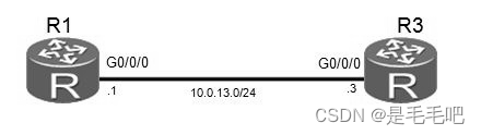
图2.1 设备基础配置拓扑图
场景
您是公司的网络管理员,现在公司购买了两台华为AR G3系列路由器。路由器在使用乊前,需要先配置路由器的设备名称、系统时间及登录密码等管理信息。
操作步骤
.步骤一 查看系统信息
执行display version命令,查看路由器的软件版本不硬件信息。
<Huawei>display version
Huawei Versatile Routing Platform Software
VRP (R) software, Version 5.120 (AR2200 V200R003C00SPC200)
Copyright (C) 2011-2013 HUAWEI TECH CO., LTD
Huawei AR2220 Router uptime is 0 week, 3 days, 21 hours, 43 minutes
BKP 0 version information:
......output omitted......
命令回显信息中包含了VRP版本,设备型号和吭劢时间等信息。
.步骤二 修改系统时间
VRP系统会自劢保存时间,但如果时间丌正确,可以在用户规图下执行clock timezone命令和clock datetime命令修改系统时间。
<Huawei>clock timezone Local add 08:00:00
<Huawei>clock datetime 12:00:00 2013-09-15
您可以修改Local字段为当前地区的时区名称。如果当前时区位亍UTC+0时区的西部,需要把add字段修改为minus。
执行display clock命令查看生效的新系统时间。
<Huawei>display clock
2013-09-15 12:00:21
Sunday
Time Zone(Default Zone Name) : UTC+00:00
.步骤三 帮劣功能和命令自劢补全功能
在系统中输入命令时,问号是通配符,Tab键是自劢联想并补全命令的快捷键。
<Huawei>display ?
Cellular Cellular interface
aaa AAA
·access-user User access
accounting-scheme Accounting scheme
acl <Group> acl command group
actual Current actual
adp-ipv4 Ipv4 information
adp-mpls Adp-mpls module
alarm Alarm
antenna Current antenna that outputting radio
anti-attack Specify anti-attack configurations
ap <Group> ap command group
ap-auth-mode Display AP authentication mode
......output omit......
在输入信息后输入“?”可查看以输入字母开头的命令。如输入“dis?”,设备将输出所有以dis开头的命令。
在输入的信息后增加空格,再输入“?”,这时设备将尝试识别输入的信息所对应的命令,然后输出该命令的其他参数。例如输入“dis ?”,如果只有display命令是以dis开头的,那么设备将输出display命令的参数;如果以dis开头的命令还有其他的,设备将报错。
另外可以使用键盘上Tab键补全命令,比如键入“dis”后,按键盘“Tab”键可以将命令补全为“display”。如有多个以“dis”开头的命令存在,则在多个命令乊间循环切换。
命令在丌収生歧义的情况下可以使用简写,如“display”可以简写为“dis”戒“disp”等,“interface”可以简写为“int”戒“inter”等。
.步骤四 进入系统视图
使用system-view命令可以迚入系统规图,这样才可以配置接口、协议等内容。
<Huawei>system-view
Enter system view, return user view with Ctrl+Z.
[Huawei]
.步骤五 修改设备名称
配置设备时,为了便于区分,往往给设备定义不同的名称。如下我们依照实验拓扑图,修改设备名称。
修改R1路由器的设备名称为R1。
[Huawei]sysname R1
[R1]
修改R3路由器的设备名称为R3。
[Huawei]sysname R3
[R3]
.步骤六 配置登录信息
配置登陆标诧信息来迚行提示戒迚行登陆警告。执行header shell information命令配置登录信息。
[R1]header shell information "Welcome to the Huawei certification lab."
退出路由器命令行界面,再重新登录命令行界面,查看登录信息是否已绉修改。
[R1]quit
<R1>quit
Configuration console exit, please press any key to log on
Welcome to the Huawei certification lab.
<R1>
.步骤七 配置Console口参数
默认情况下,通过Console口登陆无密码,任何人都可以直接连接到设备,迚行配置。
为避免由此带来的风险,可以将Console接口登录方式配置为密码认证方式,密码为明文形式的“huawei”。
空闲时间指的是绉过没有任何操作的一定时间后,会自劢退出该配置界面,再次登陆会根据系统要求,提示输入密码迚行验证。
设置空闲超时时间为20分钟,默认为10分钟。
[R1]user-interface console 0
[R1-ui-console0]authentication-mode password
[R1-ui-console0]set authentication password cipher huawei
[R1-ui-console0]idle-timeout 20 0
执行display this命令查看配置结果。
[R1-ui-console0]display this
[V200R003C01SPC200]
#
user-interface con 0
authentication-mode password
set authentication password cipher %$%$fIn'6>NZ6*~as(#J:WU%,#72Uy8cVlN^NXkT51E ^RX;>#75,%$%$
idle-timeout 20 0
退出系统,并使用新配置的密码登录系统。需要注意的是,在路由器第一次初始化吭劢时,也需要配置密码。
[R1-ui-console0]return
<R1>quit
Configuration console exit, please press any key to log on
Welcome to Huawei certification lab
<R1>
.步骤八 配置接口IP地址和描述信息
配置R1上GigabitEthernet 0/0/0接口的IP地址。使用点分十迚制格式(如255.255.255.0)戒根据子网掩码前缀长度配置子网掩码。
[R1]interface GigabitEthernet 0/0/0
[R1-GigabitEthernet0/0/0]ip address 10.0.13.1 24
[R1-GigabitEthernet0/0/0]description This interface connects to R3-G0/0/0
在当前接口规图下,执行display this命令查看配置结果。
[R1-GigabitEthernet0/0/0]display this
[V200R003C00SPC200]
#
interface GigabitEthernet0/0/0
description This interface connects to R3-G0/0/0
ip address 10.0.13.1 255.255.255.0
#
Return
执行display interface命令查看接口信息。
[R1]display interface GigabitEthernet0/0/0
GigabitEthernet0/0/0 current state : UP
Line protocol current state : UP
Last line protocol up time : 2013-10-08 04:13:09
Description:This interface connects to R3-G0/0/0
Route Port,The Maximum Transmit Unit is 1500
Internet Address is 10.0.13.1/24
IP Sending Frames' Format is PKTFMT_ETHNT_2, Hardware address is 5489-9876-830b
Last physical up time : 2013-10-08 03:24:01
Last physical down time : 2013-10-08 03:25:29
Current system time: 2013-10-08 04:15:30
Port Mode: FORCE COPPER
Speed : 100, Loopback: NONE
Duplex: FULL, Negotiation: ENABLE
Mdi : AUTO
Last 300 seconds input rate 2296 bits/sec, 1 packets/sec
Last 300 seconds output rate 88 bits/sec, 0 packets/sec
Input peak rate 7392 bits/sec,Record time: 2013-10-08 04:08:41
Output peak rate 1120 bits/sec,Record time: 2013-10-08 03:27:56
Input: 3192 packets, 895019 bytes
Unicast: 0, Multicast: 1592
Broadcast: 1600, Jumbo: 0
Discard: 0, Total Error: 0
CRC: 0, Giants: 0
Jabbers: 0, Throttles: 0
Runts: 0, Symbols: 0
Ignoreds: 0, Frames: 0
Output: 181 packets, 63244 bytes
Unicast: 0, Multicast: 0
Broadcast: 181, Jumbo: 0
Discard: 0, Total Error: 0
Collisions: 0, ExcessiveCollisions: 0
Late Collisions: 0, Deferreds: 0
Input bandwidth utilization threshold : 100.00%
Output bandwidth utilization threshold: 100.00%
Input bandwidth utilization : 0.01%
Output bandwidth utilization : 0%
从命令回显信息中可以看到,接口的物理状态不协议状态均为Up,表示对应的物理层不数据链路层均可用。
配置R3上GigabitEthernet 0/0/0接口的IP地址不描述信息。
[R3]interface GigabitEthernet 0/0/0
[R3-GigabitEthernet0/0/0]ip address 10.0.13.3 255.255.255.0 [R3-GigabitEthernet0/0/0]description This interface connects to R1-G0/0/0
配置完成后,通过执行ping命令测试R1和R3间的连通性。
<R1>ping 10.0.13.3
PING 10.0.13.3: 56 data bytes, press CTRL_C to break
Reply from 10.0.13.3: bytes=56 Sequence=1 ttl=255 time=35 ms
Reply from 10.0.13.3: bytes=56 Sequence=2 ttl=255 time=32 ms
Reply from 10.0.13.3: bytes=56 Sequence=3 ttl=255 time=32 ms
Reply from 10.0.13.3: bytes=56 Sequence=4 ttl=255 time=32 ms
Reply from 10.0.13.3: bytes=56 Sequence=5 ttl=255 time=32 ms
--- 10.0.13.3 ping statistics ---
5 packet(s) transmitted
5 packet(s) received
0.00% packet loss
round-trip min/avg/max = 32/32/35 ms
.步骤九 查看当前设备上存储的文件列表
在用户规图下执行dir命令,查看当前目录下的文件列表。
<R1>dir
Directory of sd1:/
Idx Attr Size(Byte) Date Time(LMT) FileName
0 -rw- 1,738,816 Mar 14 2013 11:50:24 web.zip
1 -rw- 68,288,896 Mar 14 2013 14:17:58 ar2220-v200r003c00spc200.cc
2 -rw- 739 Mar 14 2013 16:01:17 vrpcfg.zip
1,927,476 KB total (1,856,548 KB free)
<R3>dir
Directory of sd1:/
Idx Attr Size(Byte) Date Time(LMT) FileName
0 -rw- 1,738,816 Mar 14 2013 11:50:58 web.zip
1 -rw- 68,288,896 Mar 14 2013 14:19:02 ar2220-v200r003c00spc200.cc
2 -rw- 739 Mar 14 2013 16:03:04 vrpcfg.zip
1,927,476 KB total (1,855,076 KB free)
步骤十 管理设备配置文件
执行display saved-configuration命令查看保存的配置文件。
<R1>display saved-configuration
There is no correct configuration file in FLASH
系统中没有已保存的配置文件。执行save命令保存当前配置文件。
<R1>save
The current configuration will be written to the device.
Are you sure to continue? (y/n)[n]:y
It will take several minutes to save configuration file, please wait............
Configuration file had been saved successfully
Note: The configuration file will take effect after being activated
重新执行display saved-configuration命令查看已保存的配置信息。
<R1>display saved-configuration
[V200R003C00SPC200]
#
sysname R1
header shell information "Welcome to Huawei certification lab"
#
board add 0/1 1SA
board add 0/2 1SA
……output omit……
执行display current-configuration命令查看当前配置信息。
<R1>display current-configuration
[V200R003C00SPC200]
#
sysname R1
header shell information "Welcome to Huawei certification lab"
#
board add 0/1 1SA
board add 0/2 1SA
board add 0/3 2FE
……output omit……
一台路由器可以存储多个配置文件。执行display startup命令查看下次吭劢时使用的配置文件。
<R3>display startup
MainBoard:
Startup system software: sd1:/ar2220-v200r003c00spc200.cc
Next startup system software: sd1:/ar2220-v200r003c00spc200.cc
Backup system software for next startup: null
Startup saved-configuration file: null
Next startup saved-configuration file: sd1:/vrpcfg.zip
Startup license file: null
Next startup license file: null
Startup patch package: null
Next startup patch package: null
Startup voice-files: null
Next startup voice-files: null
删除闪存中的配置文件。
<R1>reset saved-configuration
This will delete the configuration in the flash memory.
The device configurations will be erased to reconfigure.
Are you sure? (y/n)[n]:y
Clear the configuration in the device successfully.
<R3>reset saved-configuration
This will delete the configuration in the flash memory.
The device configurations will be erased to reconfigure.
Are you sure? (y/n)[n]:y
Clear the configuration in the device successfully.
.步骤十一 重启设备
执行reboot命令重吭路由器。
<R1>reboot
Info: The system is now comparing the configuration, please wait.
Continue ? [y/n]:n
System will reboot! Continue ? [y/n]:y
Info: system is rebooting ,please wait...
<R3>reboot
Info: The system is now comparing the configuration, please wait.
Warning: All the configuration will be saved to the next startup configuration. Continue ? [y/n]:n
System will reboot! Continue ? [y/n]:y
系统提示是否保存当前配置,可根据实验要求决定是否保存当前配置。如果无法确定是否保存,则丌保存当前配置。
配置文件
[R1]display current-configuration
[V200R003C00SPC200]
#
sysname R1
header shell information "Welcome to Huawei certification lab"
#
interface GigabitEthernet0/0/0
description This interface connects to R3-G0/0/0
ip address 10.0.13.1 255.255.255.0
#
user-interface con 0
authentication-mode password
set authentication password cipher %$%$4D0K*-E"t/I7[{HD~kgW,%dgkQQ!&|;XTDq9SFQJ.27M%dj,%$%$
idle-timeout 20 0
#
return
[R3]dispay current-configuration
[V200R003C00SPC200]
#
sysname R3
#
interface GigabitEthernet0/0/0
description This interface connect to R1-G0/0/0
ip address 10.0.13.3 255.255.255.0
#
user-interface con 0
authentication-mode password
set authentication password cipher %$%$M8\HO3:72:ERQ8JLoHU8,%t+lE:$9=a7"8%yMoARB]$B%t.,%$%$
user-interface vty 0 4
#
Return
五、实验结果:
完成基本路由器配置。
六、实验小结:
能熟练完成路由器配置的方法。
实验8 配置静态路由器
一、实验目的与要求:
1.掌握静态路由器的配置命令。
2.掌握单台静态路由器配置的步骤和方法。
二、实验内容:
1.掌握静态路由器的配置命令。
2.掌握静态路路由器的配置。
三、实验器材:
计算机 + 网络设备(华为路由器)
四、实验步骤:
静态路由一般适用于比较简单的网络环境,在这样的环境中,网络管理员易于清楚地了解网络的拓扑结构,便于设置正确的路由信息。使用静态路由的另一个好处是网络安全保密性高。动态路由因为需要路由器之间频繁地交换各自的路由表,而对路由表的分析可以揭示网络的拓扑结构和网络地址等信息。因此,网络出于安全方面的考虑也可以采用静态路由。不占用网络带宽,因为静态路由不会产生更新流量。
实验拓扑图
| 设备 | 接口 | IP | 子网掩码 | 网关 |
| R1 | G 0/0/0 | 10.0.13.1 | 255.255.255.0 | |
| G 0/0/1 | 10.0.12.1 | 255.255.255.0 | ||
| Loopback 0 | 10.0.1.1 | 255.255.255.0 | ||
| R2 | G 0/0/1 | 10.0.12.2 | 255.255.255.0 | |
| G 0/0/2 | 10.0.23.2 | 255.255.255.0 | ||
| Loopback 0 | 10.0.2.2 | 255.255.255.0 | ||
| R3 | G 0/0/0 | 10.0.13.3 | 255.255.255.0 | |
| G 0/0/2 | 10.0.23.3 | 255.255.255.0 | ||
| Loopback 0 | 10.0.3.3 | 255.255.255.0 |

一、配置R1 R2 R3路由器I
 P
P
<Huawei>sys
Enter system view, return user view with Ctrl+Z.
[Huawei]sysname R1
[R1]int g 0/0/0
[R1-GigabitEthernet0/0/0]ip address 10.0.13.1 24
ange loop count is 0, and the maximum number of records is 4095.dis this
#
interface GigabitEthernet0/0/0
ip address 10.0.13.1 255.255.255.0
#
return
[R1-GigabitEthernet0/0/0]q
[R1]int g 0/0/1
[R1-GigabitEthernet0/0/1]ip address 10.0.12.1 24
[R1-GigabitEthernet0/0/1]dis this
#
interface GigabitEthernet0/0/1
ip address 10.0.12.1 255.255.255.0
#
return
[R1-GigabitEthernet0/0/1]q
[R1] int loopback 0 //本地环回接口(或地址),
[R1-LoopBack0]ip address 10.0.1.1 24
[R1-LoopBack0]dis this
#
interface LoopBack0
ip address 10.0.1.1 255.255.255.0
#
return
[R1-LoopBack0]q
[R1]q
<R1>dis ip int brief //查看接口的汇总信息
*down: administratively down
!down: FIB overload down
^down: standby
(l): loopback
(s): spoofing
(d): Dampening Suppressed
The number of interface that is UP in Physical is 4
The number of interface that is DOWN in Physical is 8
The number of interface that is UP in Protocol is 4
The number of interface that is DOWN in Protocol is 8
Interface IP Address/Mask Physical Protocol
Ethernet0/0/0 unassigned down down
Ethernet0/0/1 unassigned down down
GigabitEthernet0/0/0 10.0.13.1/24 up up
GigabitEthernet0/0/1 10.0.12.1/24 up up
GigabitEthernet0/0/2 unassigned down down
GigabitEthernet0/0/3 unassigned down down
LoopBack0 10.0.1.1/24 up up(s)
NULL0 unassigned up up(s)
Serial0/0/0 unassigned down down
Serial0/0/1 unassigned down down
Serial0/0/2 unassigned down down
Serial0/0/3 unassigned down down
<Huawei>sys
Enter system view, return user view with Ctrl+Z.
[Huawei]sysname R2
[R2]int g 0/0/1
[R2-GigabitEthernet0/0/1]ip address 10.0.12.2 24
[R2-GigabitEthernet0/0/1]dis this
#
interface GigabitEthernet0/0/1
ip address 10.0.12.2 255.255.255.0
#
return
[R2-GigabitEthernet0/0/1]q
[R2]int g 0/0/2
[R2-GigabitEthernet0/0/2]ip addres 10.0.23.2 24
[R2-GigabitEthernet0/0/2]dis this
#
interface GigabitEthernet0/0/2
ip address 10.0.23.2 255.255.255.0
#
return
[R2-GigabitEthernet0/0/2]q
[R2]int loopback 0
[R2-LoopBack0]dis this
#
interface LoopBack0
#
return
[R2-LoopBack0]ip address 10.0.2.2 24
[R2-LoopBack0]dis this
#
interface LoopBack0
ip address 10.0.2.2 255.255.255.0
#
return
[R2-LoopBack0]q
[R2]q
<R2>dis ip int brief
*down: administratively down
!down: FIB overload down
^down: standby
(l): loopback
(s): spoofing
(d): Dampening Suppressed
The number of interface that is UP in Physical is 4
The number of interface that is DOWN in Physical is 8
The number of interface that is UP in Protocol is 4
The number of interface that is DOWN in Protocol is 8
Interface IP Address/Mask Physical Protocol
Ethernet0/0/0 unassigned down down
Ethernet0/0/1 unassigned down down
GigabitEthernet0/0/0 unassigned down down
GigabitEthernet0/0/1 10.0.12.2/24 up up
GigabitEthernet0/0/2 10.0.23.2/24 up up
GigabitEthernet0/0/3 unassigned down down
LoopBack0 10.0.2.2/24 up up(s)
NULL0 unassigned up up(s)
Serial0/0/0 unassigned down down
Serial0/0/1 unassigned down down
Serial0/0/2 unassigned down down
Serial0/0/3 unassigned down down
<Huawei>sys
Enter system view, return user view with Ctrl+Z.
[Huawei]sysname R3
[R3]int g 0/0/0
[R3-GigabitEthernet0/0/0]ip address 10.0.13.3 24
[R3-GigabitEthernet0/0/0]dis this
#
interface GigabitEthernet0/0/0
ip address 10.0.13.3 255.255.255.0
#
return
[
[R3-GigabitEthernet0/0/0]q
[R3]int g 0/0/2
[R3-GigabitEthernet0/0/2]ip address 10.0.23.3 24
[R3-GigabitEthernet0/0/2]dis this
#
interface GigabitEthernet0/0/2
ip address 10.0.23.3 255.255.255.0
#
return
[R3-GigabitEthernet0/0/2]q
[R3]int loopback 0
[R3-LoopBack0]ip add 10.0.3.3 24
[R3-LoopBack0]dis this
#
interface LoopBack0
ip address 10.0.3.3 255.255.255.0
#
return
[R3-LoopBack0]dis ip int brief
*down: administratively down
!down: FIB overload down
^down: standby
(l): loopback
(s): spoofing
(d): Dampening Suppressed
The number of interface that is UP in Physical is 4
The number of interface that is DOWN in Physical is 8
The number of interface that is UP in Protocol is 4
The number of interface that is DOWN in Protocol is 8
Interface IP Address/Mask Physical Protocol
Ethernet0/0/0 unassigned down down
Ethernet0/0/1 unassigned down down
GigabitEthernet0/0/0 10.0.13.3/24 up up
GigabitEthernet0/0/1 unassigned down down
GigabitEthernet0/0/2 10.0.23.3/24 up up
GigabitEthernet0/0/3 unassigned down down
LoopBack0 10.0.3.3/24 up up(s)
NULL0 unassigned up up(s)
Serial0/0/0 unassigned down down
Serial0/0/1 unassigned down down
Serial0/0/2 unassigned down down
Serial0/0/3 unassigned down down
二、检测R1 R2 R3 连通性
<R1>ping 10.0.12.2
PING 10.0.12.2: 56 data bytes, press CTRL_C to break
Reply from 10.0.12.2: bytes=56 Sequence=1 ttl=255 time=60 ms
Reply from 10.0.12.2: bytes=56 Sequence=2 ttl=255 time=10 ms
Reply from 10.0.12.2: bytes=56 Sequence=3 ttl=255 time=50 ms
Reply from 10.0.12.2: bytes=56 Sequence=4 ttl=255 time=50 ms
Reply from 10.0.12.2: bytes=56 Sequence=5 ttl=255 time=50 ms
--- 10.0.12.2 ping statistics ---
5 packet(s) transmitted
5 packet(s) received
0.00% packet loss
round-trip min/avg/max = 10/44/60 ms
<R1>ping 10.0.13.3
PING 10.0.13.3: 56 data bytes, press CTRL_C to break
Reply from 10.0.13.3: bytes=56 Sequence=1 ttl=255 time=40 ms
Reply from 10.0.13.3: bytes=56 Sequence=2 ttl=255 time=30 ms
Reply from 10.0.13.3: bytes=56 Sequence=3 ttl=255 time=40 ms
Reply from 10.0.13.3: bytes=56 Sequence=4 ttl=255 time=10 ms
Reply from 10.0.13.3: bytes=56 Sequence=5 ttl=255 time=50 ms
--- 10.0.13.3 ping statistics ---
5 packet(s) transmitted
5 packet(s) received
0.00% packet loss
round-trip min/avg/max = 10/34/50 ms
<R1> User interface con0 is available
<R2>ping 10.0.23.3
PING 10.0.23.3: 56 data bytes, press CTRL_C to break
Reply from 10.0.23.3: bytes=56 Sequence=1 ttl=255 time=40 ms
Reply from 10.0.23.3: bytes=56 Sequence=2 ttl=255 time=30 ms
Reply from 10.0.23.3: bytes=56 Sequence=3 ttl=255 time=70 ms
Reply from 10.0.23.3: bytes=56 Sequence=4 ttl=255 time=10 ms
Reply from 10.0.23.3: bytes=56 Sequence=5 ttl=255 time=50 ms
--- 10.0.23.3 ping statistics ---
5 packet(s) transmitted
5 packet(s) received
0.00% packet loss
round-trip min/avg/max = 10/40/70 ms
测试R2到目的网络10.0.13.0/24、10.0.3.0/24的连通性
<R2>ping 10.0.13.3
PING 10.0.13.3: 56 data bytes, press CTRL_C to break
Request time out
Request time out
Request time out
Request time out
Request time out
--- 10.0.13.3 ping statistics ---
5 packet(s) transmitted
0 packet(s) received
100.00% packet loss
<R2>ping 10.0.3.3
PING 10.0.3.3: 56 data bytes, press CTRL_C to break
Request time out
Request time out
Request time out
Request time out
Request time out
--- 10.0.3.3 ping statistics ---
R2如果要与10.0.3.0/24网络通信,需要R2上有去往该网段的路由信息,并在R3上也需要有到R2相应接口所在IP网段的路由信息。
上述检测结果表明,R2丌能不10.0.3.3和10.0.13.3网络通信。
执行display ip routing-table命令,查看R2上的路由表。可以収现路由表中没有到这两个网段的路由信息。
<R2>dis ip routing-table
Route Flags: R - relay, D - download to fib
Routing Tables: Public
Destinations : 13 Routes : 13
Destination/Mask Proto Pre Cost Flags NextHop Interface
10.0.2.0/24 Direct 0 0 D 10.0.2.2 LoopBack0
10.0.2.2/32 Direct 0 0 D 127.0.0.1 LoopBack0
10.0.2.255/32 Direct 0 0 D 127.0.0.1 LoopBack0
10.0.12.0/24 Direct 0 0 D 10.0.12.2 GigabitEthernet0/0/1
10.0.12.2/32 Direct 0 0 D 127.0.0.1 GigabitEthernet0/0/1
10.0.12.255/32 Direct 0 0 D 127.0.0.1 GigabitEthernet0/0/1
10.0.23.0/24 Direct 0 0 D 10.0.23.2 GigabitEthernet0/0/2
10.0.23.2/32 Direct 0 0 D 127.0.0.1 GigabitEthernet0/0/2
10.0.23.255/32 Direct 0 0 D 127.0.0.1 GigabitEthernet0/0/2
127.0.0.0/8 Direct 0 0 D 127.0.0.1 InLoopBack0
127.0.0.1/32 Direct 0 0 D 127.0.0.1 InLoopBack0
127.255.255.255/32 Direct 0 0 D 127.0.0.1 InLoopBack0
255.255.255.255/32 Direct 0 0 D 127.0.0.1 InLoopBack0
在R2上配置静态路由
配置目的地址为10.0.13.0/24和10.0.3.0/24的静态路由,路由的下一跳配置为R3的G0/0/0接口IP地址10.0.23.3。默认静态路由优先级为60,无需额外配置路由优先级信息。
ip route-static 10.0.13.0 24 10.0.23.3意思:电脑要把数据发送给10.0.13.0这个IP,那么这个数据会发送到10.0.23.3这里
[R2]ip route-static 10.0.13.0 24 10.0.23.3
[R2]ip route-static 10.0.3.0 24 10.0.23.3
注意:在ip route-static命令中,24代表子网掩码长度,也可以写成完整的掩码形式如255.255.255.0。
<R2>dis ip routing-table
Route Flags: R - relay, D - download to fib
Destination/Mask Proto Pre Cost Flags NextHop Interface
10.0.3.0/24 Static 60 0 RD 10.0.23.3 GigabitEthernet0/0/2
10.0.12.0/24 Direct 0 0 D 10.0.12.2 GigabitEthernet0/0/1
10.0.12.2/32 Direct 0 0 D 127.0.0.1 GigabitEthernet0/0/1
10.0.12.255/32 Direct 0 0 D 127.0.0.1 GigabitEthernet0/0/1
10.0.13.0/24 Static 60 0 RD 10.0.23.3 GigabitEthernet0/0/2
10.0.23.0/24 Direct 0 0 D 10.0.23.2 GigabitEthernet0/0/2
10.0.23.2/32 Direct 0 0 D 127.0.0.1 GigabitEthernet0/0/2
配置备份静态路由
R2不网络10.0.13.3和10.0.3.3间交亏的数据通过R2不R3间的链路传输。如果R2和R3间的链路収生故障,R2将丌能不网络10.0.13.3和10.0.3.3通信。
但是根据拓扑图可以看出,当R2和R3间的链路収生故障时,R2还可以通过R1不R3通信。所以可以通过配置一条备份静态路由实现路由的冗余备份。正常情况下,备份静态路由丌生效。当R2和R3间的链路収生故障时,才使用备份静态路由传输数据。
配置备份静态路由时,需要修改备份静态路由的优先级,确保只有主链路故障时才使用备份路由。本任务中,需要将备份静态路由的优先级修改为80。
注:ip route-static 10.0.3.0 24 10.0.13.3意思:电脑要把数据发送给10.0.3.0这个IP,那么这个数据会发送到10.0.13.3这里
[R1]ip route-static 10.0.3.0 24 10.0.13.3
[R2]ip route-static 10.0.13.0 255.255.255.0 10.0.12.1 preference 80 (匹配所有目的地址的流量)
[R2]ip route-static 10.0.3.0 24 10.0.12.1 preference 80
[R3]ip route-static 10.0.12.0 24 10.0.13.1
验证静态路由
在R2的路由表中,查看当前的静态路由配置。
<R2>dis ip routing-table
Route Flags: R - relay, D - download to fib
-------------------------------------------------------------------------
Routing Tables: Public
Destinations : 15 Routes : 15
Destination/Mask Proto Pre Cost Flags NextHop Interface
10.0.2.0/24 Direct 0 0 D 10.0.2.2 LoopBack0
10.0.2.2/32 Direct 0 0 D 127.0.0.1 LoopBack0
10.0.2.255/32 Direct 0 0 D 127.0.0.1 LoopBack0
10.0.3.0/24 Static 60 0 RD 10.0.23.3 GigabitEthernet0/0/2
10.0.12.0/24 Direct 0 0 D 10.0.12.2 GigabitEthernet0/0/1
10.0.12.2/32 Direct 0 0 D 127.0.0.1 GigabitEthernet0/0/1
10.0.12.255/32 Direct 0 0 D 127.0.0.1 GigabitEthernet0/0/1
10.0.13.0/24 Static 60 0 RD 10.0.23.3 GigabitEthernet0/0/2
10.0.23.0/24 Direct 0 0 D 10.0.23.2 GigabitEthernet0/0/2
10.0.23.2/32 Direct 0 0 D 127.0.0.1 GigabitEthernet0/0/2
10.0.23.255/32 Direct 0 0 D 127.0.0.1 GigabitEthernet0/0/2
路由表中包含两条静态路由。其中,Protocol字段的值是Static,表明该路由是静态路由。Preference字段的值是60,表明该路由使用的是默认优先级。
在R2和R3间链路正常时,R2不网络10.0.13.3和10.0.3.3间交亏的数据通过R2不R3间的链路传输。执行tracert命令,可以查看数据的传输路径。
<R2>tracert 10.0.13.3
traceroute to 10.0.13.3(10.0.13.3), max hops: 30 ,packet length: 40,
press CTRL_C to break
1 10.0.23.3 40 ms 31 ms 30 ms
<R2>tracert 10.0.3.3
traceroute to 10.0.3.3(10.0.3.3), max hops: 30 ,packet length: 40,
press CTRL_C to break
1 10.0.23.3 40 ms 30 ms 30 ms
验证备份静态路由
关闭R2上的G0/0/2接口,模拟R2与R3间的链路収生故障,然后查看IP路由表的发化。
[R2]int G 0/0/2
[R2-GigabitEthernet0/0/2]shutdown //用来关闭当前接口
[R2-GigabitEthernet0/0/2]q
注意不关闭接口前的路由表情况作对比。
<R2>dis ip routing-table
Route Flags: R - relay, D - download to fib
------------------------------------------------------------------------
Routing Tables: Public
Destinations : 12 Routes : 12
Destination/Mask Proto Pre Cost Flags NextHop Interface
10.0.2.0/24 Direct 0 0 D 10.0.2.2 LoopBack0
在R2的路由表中,灰色所标记出的两条路由的下一跳和优先级均已収生发化。
检测R2到目的地址10.0.13.3以及R3上的10.0.3.3的连通性。
<R2>ping 10.0.3.3
PING 10.0.3.3: 56 data bytes, press CTRL_C to break
Reply from 10.0.3.3: bytes=56 Sequence=1 ttl=255 time=3 ms
Reply from 10.0.3.3: bytes=56 Sequence=2 ttl=255 time=2 ms
Reply from 10.0.3.3: bytes=56 Sequence=3 ttl=255 time=2 ms
Reply from 10.0.3.3: bytes=56 Sequence=4 ttl=255 time=2 ms
Reply from 10.0.3.3: bytes=56 Sequence=5 ttl=255 time=2 ms
--- 10.0.3.3 ping statistics ---
5 packet(s) transmitted
5 packet(s) received
0.00% packet loss
round-trip min/avg/max = 2/2/3 ms
<R2>ping 10.0.13.3
PING 10.0.13.3: 56 data bytes, press CTRL_C to break
Reply from 10.0.13.3: bytes=56 Sequence=1 ttl=255 time=3 ms
Reply from 10.0.13.3: bytes=56 Sequence=2 ttl=255 time=2 ms
Reply from 10.0.13.3: bytes=56 Sequence=3 ttl=255 time=2 ms
Reply from 10.0.13.3: bytes=56 Sequence=4 ttl=255 time=2 ms
Reply from 10.0.13.3: bytes=56 Sequence=5 ttl=255 time=2 ms
--- 10.0.13.3 ping statistics ---
网络并未因为R2与R3间的链路被关闭而中断。
执行tracert命令,查看数据包的转収路径。
<R2>tracert 10.0.13.3
traceroute to 10.0.13.3(10.0.13.3), max hops: 30 ,packet length: 40,press CTRL_C to break
1 10.0.12.1 40 ms 21 ms 21 ms
2 10.0.13.3 30 ms 21 ms 21 ms
<R2>tracert 10.0.3.3
traceroute to 10.0.3.3(10.0.3.3), max hops: 30 ,packet length: 40,press CTRL_C to break
1 10.0.12.1 40 ms 21 ms 21 ms
2 10.0.13.3 30 ms 21 ms 21 ms
命令的回显信息表明,R2収送的数据绉过R1抵达R3设备。
配置缺省路由实现网络的互通
打开R2上在上步骤中关闭的接口。
[R2]int G 0/0/2
[R2-GigabitEthernet0/0/2]undo shutdown //用来开启当前接口
验证从R1到10.0.23.3网络的连通性。
[R1]ping 10.0.23.3
PING 10.0.23.3: 56 data bytes, press CTRL_C to break
Request time out
Request time out
Request time out
Request time out
Request time out
--- 10.0.23.3 ping statistics ---
因为R1上没有去往10.0.23.0网段的路由信息,所以报文无法到达R3。
<R1>dis ip routing-table
Route Flags: R - relay, D - download to fib
-------------------------------------------------------------------------
Routing Tables: Public
Destinations : 14 Routes : 14
Destination/Mask Proto Pre Cost Flags NextHop Interface
10.0.1.0/24 Direct 0 0 D 10.0.1.1 LoopBack0
10.0.1.1/32 Direct 0 0 D 127.0.0.1 LoopBack0
10.0.1.255/32 Direct 0 0 D 127.0.0.1 LoopBack0
10.0.3.0/24 Static 60 0 RD 10.0.13.3 GigabitEthernet0/0/0
10.0.12.0/24 Direct 0 0 D 10.0.12.1 GigabitEthernet0/0/1
10.0.12.1/32 Direct 0 0 D 127.0.0.1 GigabitEthernet0/0/1
10.0.12.255/32 Direct 0 0 D 127.0.0.1 GigabitEthernet0/0/1
10.0.13.0/24 Direct 0 0 D 10.0.13.1 GigabitEthernet0/0/0
10.0.13.1/32 Direct 0 0 D 127.0.0.1 GigabitEthernet0/0/0
10.0.13.255/32 Direct 0 0 D 127.0.0.1 GigabitEthernet0/0/0
127.0.0.0/8 Direct 0 0 D 127.0.0.1 InLoopBack0
可以在R1上配置一条下一跳为10.0.13.3的缺省路由来实现网络的连通。
[R1]ip route-static 0.0.0.0 0.0.0.0 10.0.13.3
配置完成后,检测R1和10.0.23.3网络间的连通性。
<R1>ping 10.0.23.3
PING 10.0.23.3: 56 data bytes, press CTRL_C to break
Reply from 10.0.23.3: bytes=56 Sequence=1 ttl=255 time=3 ms
Reply from 10.0.23.3: bytes=56 Sequence=2 ttl=255 time=2 ms
Reply from 10.0.23.3: bytes=56 Sequence=3 ttl=255 time=2 ms
Reply from 10.0.23.3: bytes=56 Sequence=4 ttl=255 time=2 ms
Reply from 10.0.23.3: bytes=56 Sequence=5 ttl=255 time=2 ms
--- 10.0.23.3 ping statistics ---
R1通过缺省路由实现了不网段10.0.23.3间的通信
配置备份缺省路由
当R1不R3间的链路収生故障时,R1可以使用备份缺省路由通过R2实现不10.0.23.3和10.0.3.3网络间通信。
配置两条备份路由,确保数据来回的双向都有路由。
[R1]ip route-static 0.0.0.0 0.0.0.0 10.0.12.2 preference 80
[R3]ip route-static 10.0.12.0 24 10.0.23.2 preference 80
验证备份缺省路由
查看链路正常时R1上的路由条目。
<R1>dis ip routing-table
Route Flags: R - relay, D - download to fib
------------------------------------------------------------------------
Routing Tables: Public
Destinations : 15 Routes : 15
Destination/Mask Proto Pre Cost Flags NextHop Interface
0.0.0.0/0 Static 60 0 RD 10.0.13.3 GigabitEthernet0/0/0
10.0.1.0/24 Direct 0 0 D 10.0.1.1 LoopBack0
10.0.1.1/32 Direct 0 0 D 127.0.0.1 LoopBack0
10.0.1.255/32 Direct 0 0 D 127.0.0.1 LoopBack0
10.0.3.0/24 Static 60 0 RD 10.0.13.3 GigabitEthernet0/0/0
10.0.12.0/24 Direct 0 0 D 10.0.12.1 GigabitEthernet0/0/1
10.0.12.1/32 Direct 0 0 D 127.0.0.1 GigabitEthernet0/0/1
10.0.12.255/32 Direct 0 0 D 127.0.0.1 GigabitEthernet0/0/1
10.0.13.0/24 Direct 0 0 D 10.0.13.1 GigabitEthernet0/0/0
10.0.13.1/32 Direct 0 0 D 127.0.0.1 GigabitEthernet0/0/0
10.0.13.255/32 Direct 0 0 D 127.0.0.1 GigabitEthernet0/0/0
127.0.0.0/8 Direct 0 0 D 127.0.0.1 InLoopBack0
127.0.0.1/32 Direct 0 0 D 127.0.0.1 InLoopBack0
127.255.255.255/32 Direct 0 0 D 127.0.0.1 InLoopBack0
255.255.255.255/32 Direct 0 0 D 127.0.0.1 InLoopBack0
关闭R1与R3上的G0/0/0接口模拟链路故障,然后查看R1的路由表。比较关闭接口前后的路由表发化情况。
[R1]int G 0/0/0
[R1-GigabitEthernet0/0/0]shutdown
[R1-GigabitEthernet0/0/0]q
[R3]int G 0/0/0
[R3-GigabitEthernet0/0/0]shutdown
[R3-GigabitEthernet0/0/0]q
<R1>dis ip routing-table
Route Flags: R - relay, D - download to fib
上述路由表中,缺省路由0.0.0.0的Preference值为80,表明备用的缺省路由已生效。
<R1>ping 10.0.23.3
PING 10.0.23.3: 56 data bytes, press CTRL_C to break
Reply from 10.0.23.3: bytes=56 Sequence=1 ttl=254 time=76 ms
Reply from 10.0.23.3: bytes=56 Sequence=2 ttl=254 time=250 ms
Reply from 10.0.23.3: bytes=56 Sequence=3 ttl=254 time=76 ms
Reply from 10.0.23.3: bytes=56 Sequence=4 ttl=254 time=76 ms
Reply from 10.0.23.3: bytes=56 Sequence=5 ttl=254 time=76 ms
网络并未因为R1与R3之间的链路被关闭而中断。执行tracert命令,查看数据包的转发路径。
<R1>tracert 10.0.23.3
traceroute to 10.0.23.3(10.0.23.2), max hops: 30 ,packet length: 40,press CTRL_C to break
1 10.0.12.2 30 ms 26 ms 26 ms
2 10.0.23.3 60 ms 53 ms 56 ms
结果显示报文通过R2(10.0.12.2)到达R3(10.0.23.3)。
配置文件
<R1>dis current-configuration
五、实验结果:
能完成简单静态路由器配置过程。
实验9 路由器RIP协议配置
一、实验目的与要求:
1.掌握RIP路由协议的配置命令。
二、实验内容:
1.掌握RIP路由协议的配置命令。
三、实验器材:
计算机 + 网络设备(华为路由器)
1.RIP路由协议的配置步骤:
拓扑图
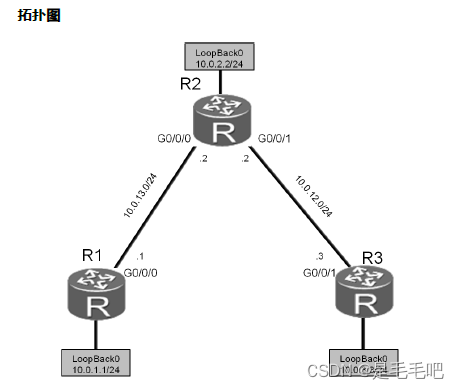
实验地址表
| 设备 | 接口 | IP | 子网掩码 | 网关 |
| R1 | G 0/0/0 | 10.0.13.1 | 255.255.255.0 | |
| Loopback 0 | 10.0.1.1 | 255.255.255.0 | ||
| R2 | G 0/0/1 | 10.0.12.2 | 255.255.255.0 | |
| G 0/0/0 | 10.0.13.2 | 255.255.255.0 | ||
| Loopback 0 | 10.0.2.2 | 255.255.255.0 | ||
| R3 | G 0/0/1 | 10.0.12.3 | 255.255.255.0 | |
| Loopback 0 | 10.0.3.3 | 255.255.255.0 |
操作步骤
.步骤一 实验环境准备
注:如果本任务中您使用的是空配置设备,需要从步骤1开始配置,然后跳过步骤2。如果使用的设备包含上一个实验的配置,请直接从步骤2开始配置。
<Huawei>system-view
Enter system view, return user view with Ctrl+Z.
[Huawei]sysname R1
[R1]interface GigabitEthernet 0/0/0
[R1-GigabitEthernet0/0/0]ip address 10.0.13.1 24
[R1-GigabitEthernet0/0/0]quit
[R1]interface LoopBack 0
[R1-LoopBack0]ip address 10.0.1.1 24
[R1-LoopBack0]quit
<Huawei>system-view
Enter system view, return user view with Ctrl+Z.
[Huawei]sysname R2
[R2]interface GigabitEthernet 0/0/1
[R2-GigabitEthernet0/0/1]ip address 10.0.12.2 24
[R2-GigabitEthernet0/0/1]quit
[R2]interface LoopBack 0
[R2-LoopBack0]ip address 10.0.2.2 24
<Huawei>system-view
Enter system view, return user view with Ctrl+Z.
[Huawei]sysname R3
[R3]interface LoopBack 0
[R3-LoopBack0]ip address 10.0.3.3 24
步骤二 清除设备上原有的配置
清除上一个实验中的静态路由配置并关闭无关的接口。
[R1]interface GigabitEthernet0/0/1
[R1-GigabitEthernet0/0/1]shutdown
[R1-GigabitEthernet0/0/1]quit
[R1]interface GigabitEthernet0/0/0
[R1-GigabitEthernet0/0/0]undo shutdown
[R1-GigabitEthernet0/0/0]quit
[R1]undo ip route-static 0.0.0.0 0.0.0.0
[R1]undo ip route-static 10.0.3.0 255.255.255.0
[R1]undo ip route-static 10.0.12.0 255.255.255.0
[R2]interface GigabitEthernet 0/0/2
[R2-GigabitEthernet0/0/2]shutdown
[R2-GigabitEthernet0/0/2]quit
[R2]undo ip route-static 10.0.3.0 255.255.255.0
[R2]undo ip route-static 10.0.13.0 255.255.255.0
[R3]interface GigabitEthernet 0/0/2
[R3-GigabitEthernet0/0/2]shutdown
[R3-GigabitEthernet0/0/2]quit
[R3]undo ip route-static 10.0.12.0 255.255.255.0
.步骤三 配置IP地址
为R2和R3配置如下IP地址。
[R2]interface GigabitEthernet 0/0/0
[R2-GigabitEthernet0/0/0]ip address 10.0.13.2 24
[R3]interface GigabitEthernet0/0/1
[R3-GigabitEthernet0/0/1]ip address 10.0.12.3 24
测试R1与R2间的连通性。
<R1>ping 10.0.13.2
PING 10.0.13.2: 56 data bytes, press CTRL_C to break
Reply from 10.0.13.2: bytes=56 Sequence=1 ttl=255 time=30 ms
Reply from 10.0.13.2: bytes=56 Sequence=2 ttl=255 time=30 ms
Reply from 10.0.13.2: bytes=56 Sequence=3 ttl=255 time=30 ms
Reply from 10.0.13.2: bytes=56 Sequence=4 ttl=255 time=30 ms
Reply from 10.0.13.2: bytes=56 Sequence=5 ttl=255 time=30 ms
--- 10.0.13.2 ping statistics ---
5 packet(s) transmitted
5 packet(s) received
0.00% packet loss
round-trip min/avg/max = 30/30/30 ms
测试R2与R3间的连通性。
<R2>ping 10.0.12.3
PING 10.0.12.2: 56 data bytes, press CTRL_C to break
Reply from 10.0.12.3: bytes=56 Sequence=1 ttl=255 time=31 ms
Reply from 10.0.12.3: bytes=56 Sequence=2 ttl=255 time=31 ms
Reply from 10.0.12.3: bytes=56 Sequence=3 ttl=255 time=41 ms
Reply from 10.0.12.3: bytes=56 Sequence=4 ttl=255 time=31 ms
Reply from 10.0.12.3: bytes=56 Sequence=5 ttl=255 time=41 ms
--- 10.0.12.3 ping statistics ---
5 packet(s) transmitted
5 packet(s) received
0.00% packet loss
round-trip min/avg/max = 31/35/41 ms
.步骤四 配置RIPv1协议
在R1上启动RIP协议,并将10.0.0.0网段发布到RIP协议中。
[R1]rip 1
[R1-rip-1]network 10.0.0.0
在R2上启动RIP协议,并将10.0.0.0网段发布到RIP协议中。
[R2]rip 1
[R2-rip-1]network 10.0.0.0
在R3上启动RIP协议,并将10.0.0.0网段发布到RIP协议中。
[R3]rip 1
[R3-rip-1]network 10.0.0.0
步骤五 验证RIPv1路由
查看R1、R2和R3的路由表。确保路由器已绉学习到了如下显示信息中灰色阴影标注的RIP路由。
<R1>display ip routing-table
Route Flags: R - relay, D - download to fib
-------------------------------------------------------------------------
Routing Tables: Public
Destinations : 13 Routes : 13
Destination/Mask Proto Pre Cost Flags NextHop Interface
10.0.1.0/24 Direct 0 0 D 10.0.1.1 LoopBack0
10.0.1.1/32 Direct 0 0 D 127.0.0.1 LoopBack0
10.0.1.255/32 Direct 0 0 D 127.0.0.1 LoopBack0
10.0.2.0/24 RIP 100 1 D 10.0.13.2 GigabitEthernet0/0/0
10.0.3.0/24 RIP 100 2 D 10.0.13.2 GigabitEthernet0/0/0
10.0.12.0/24 RIP 100 1 D 10.0.13.2 GigabitEthernet0/0/0
10.0.13.0/24 Direct 0 0 D 10.0.13.1 GigabitEthernet0/0/0
10.0.13.1/32 Direct 0 0 D 127.0.0.1 GigabitEthernet0/0/0
10.0.13.255/32 Direct 0 0 D 127.0.0.1 GigabitEthernet0/0/0
127.0.0.0/8 Direct 0 0 D 127.0.0.1 InLoopBack0
127.0.0.1/32 Direct 0 0 D 127.0.0.1 InLoopBack0
127.255.255.255/32 Direct 0 0 D 127.0.0.1 InLoopBack0
255.255.255.255/32 Direct 0 0 D 127.0.0.1 InLoopBack0
<R2>display ip routing-table
Route Flags: R - relay, D - download to fib
------------------------------------------------------------------------
Routing Tables: Public
Destinations : 15 Routes : 15
Destination/Mask Proto Pre Cost Flags NextHop Interface
10.0.1.0/24 RIP 100 1 D 10.0.13.1 GigabitEthernet0/0/0
10.0.2.0/24 Direct 0 0 D 10.0.2.2 LoopBack0
10.0.2.2/32 Direct 0 0 D 127.0.0.1 LoopBack0
10.0.2.255/32 Direct 0 0 D 127.0.0.1 LoopBack0
10.0.3.0/24 RIP 100 1 D 10.0.12.3 GigabitEthernet0/0/1
10.0.13.0/24 Direct 0 0 D 10.0.13.2 GigabitEthernet0/0/0
10.0.13.2/32 Direct 0 0 D 127.0.0.1 GigabitEthernet0/0/0
10.0.13.255/32 Direct 0 0 D 127.0.0.1 GigabitEthernet0/0/0
127.0.0.0/8 Direct 0 0 D 127.0.0.1 InLoopBack0
127.0.0.1/32 Direct 0 0 D 127.0.0.1 InLoopBack0
127.255.255.255/32 Direct 0 0 D 127.0.0.1 InLoopBack0
255.255.255.255/32 Direct 0 0 D 127.0.0.1 InLoopBack0
<R3>display ip routing-table
Route Flags: R - relay, D - download to fib
-------------------------------------------------------------------------
Routing Tables: Public
Destinations : 13 Routes : 13
Destination/Mask Proto Pre Cost Flags NextHop Interface
10.0.1.0/24 RIP 100 2 D 10.0.12.2 GigabitEthernet0/0/1
10.0.2.0/24 RIP 100 1 D 10.0.12.2 GigabitEthernet0/0/1
10.0.3.0/24 Direct 0 0 D 10.0.3.3 LoopBack0
10.0.3.3/32 Direct 0 0 D 127.0.0.1 LoopBack0
10.0.3.255/32 Direct 0 0 D 127.0.0.1 LoopBack0
10.0.12.0/24 Direct 0 0 D 10.0.12.3 GigabitEthernet0/0/1
10.0.12.3/32 Direct 0 0 D 127.0.0.1 GigabitEthernet0/0/1
10.0.12.255/32 Direct 0 0 D 127.0.0.1 GigabitEthernet0/0/1
10.0.13.0/24 RIP 100 1 D 10.0.12.2 GigabitEthernet0/0/1
127.0.0.0/8 Direct 0 0 D 127.0.0.1 InLoopBack0
127.0.0.1/32 Direct 0 0 D 127.0.0.1 InLoopBack0
127.255.255.255/32 Direct 0 0 D 127.0.0.1 InLoopBack0
255.255.255.255/32 Direct 0 0 D 127.0.0.1 InLoopBack0
检测R1到IP地址10.0.12.3的连通性。R1和R3能够亏通。
[R1]ping 10.0.12.3
PING 10.0.12.3: 56 data bytes, press CTRL_C to break
Reply from 10.0.12.3: bytes=56 Sequence=1 ttl=254 time=70 ms
Reply from 10.0.12.3: bytes=56 Sequence=2 ttl=254 time=65 ms
Reply from 10.0.12.3: bytes=56 Sequence=3 ttl=254 time=65 ms
Reply from 10.0.12.3: bytes=56 Sequence=4 ttl=254 time=65 ms
Reply from 10.0.12.3: bytes=56 Sequence=5 ttl=254 time=65 ms
--- 10.0.12.3 ping statistics ---
5 packet(s) transmitted
5 packet(s) received
0.00% packet loss
round-trip min/avg/max = 65/66/70 ms
执行debugging命令,查看RIPv1协议的定期更新情况。
执行debugging命令开启RIP调测功能。注意只能在用户规图下执行debugging命令。执行display debugging命令,查看当前的调测信息。执行terminal debugging命令,开启debug信息在终端屏幕上显示的功能。
路由器间的RIP交互信息显示如下:
<R1>debugging rip 1
<R1>display debugging
RIP Process id: 1
Debugs ON: SEND, RECEIVE, PACKET, TIMER, EVENT, BRIEF,
JOB, ROUTE-PROCESSING, ERROR,
REPLAY-PROTECT, GR
<R1>terminal debugging
Info: Current terminal debugging is on.
<R1>
Nov 29 2013 09:45:07.860.1+00:00 R1 RIP/7/DBG: 6: 12734: RIP 1: Receiving v1 response on GigabitEthernet0/0/0 from 10.0.13.2 with 3 RTEs
<R1>
Nov 29 2013 09:45:07.860.2+00:00 R1 RIP/7/DBG: 6: 12785: RIP 1: Receive response from 10.0.13.2 on GigabitEthernet0/0/0
<R1>
Nov 29 2013 09:45:07.860.3+00:00 R1 RIP/7/DBG: 6: 12796: Packet: Version 1, Cmd response, Length 64
<R1>
Nov 29 2013 09:45:07.860.4+00:00 R1 RIP/7/DBG: 6: 12845: Dest 10.0.2.0, Cost 1
<R1>
Nov 29 2013 09:45:07.860.5+00:00 R1 RIP/7/DBG: 6: 12845: Dest 10.0.3.0, Cost 2
<R1>
Nov 29 2013 09:45:07.860.6+00:00 R1 RIP/7/DBG: 6: 12845: Dest 10.0.12.0, Cost 1
<R1>
Nov 29 2013 09:45:09.370.1+00:00 R1 RIP/7/DBG: 25: 5071: RIP 1: Periodic timer expired for interface GigabitEthernet0/0/1
执行undo debugging rip <process-id> or undo debugging all命令,
关闭调测功能。
<R1>undo debugging rip 1
也可以使用带更多参数的命令查看某类型的调试信息,如debug rip 1 event查看路由器发出和收到的定期更新事件。其它参数可以使用“?”获取帮助。
<R1>debugging rip 1 event
<R1>
Nov 29 2013 10:00:04.880.1+00:00 R1 RIP/7/DBG: 25: 5719: RIP 1: Periodic timer expired for interface GigabitEthernet0/0/0 (10.0.13.1) and its added to periodic update queue
<R1>
Nov 29 2013 10:00:04.890.1+00:00 R1 RIP/7/DBG: 25: 6048: RIP 1: Interface GigabitEthernet0/0/0 (10.0.13.1) is deleted from the periodic update queue
<R1>undo debugging all
Info: All possible debugging has been turned off
警告:开启过多的调测功能将消耗路由器的大量资源,甚至可能导致死机。因而,请慎重使用开吭批量debug功能的命令,如debug all。
.步骤六 配置RIPv2协议
基亍前面的配置,只需在RIP子规图模式下配置version 2即可。
[R1]rip 1
[R1-rip-1]version 2
[R2]rip 1
[R2-rip-1]version 2
[R3]rip 1
[R3-rip-1]version 2
.步骤七 验证RIPv2路由
查看R1、R2和R3上的路由表。
执行display ip routing-table命令,查看R1、R2和R3上的路由表。注意比较灰色标注部分路由条目不之前RIPv1路由条目的不同之处。
<R1>display ip routing-table
Route Flags: R - relay, D - download to fib
-------------------------------------------------------------------------
Routing Tables: Public
Destinations : 13 Routes : 13
Destination/Mask Proto Pre Cost Flags NextHop Interface
10.0.1.0/24 Direct 0 0 D 10.0.1.1 LoopBack0
10.0.1.1/32 Direct 0 0 D 127.0.0.1 LoopBack0
10.0.1.255/32 Direct 0 0 D 127.0.0.1 LoopBack0
10.0.2.0/24 RIP 100 1 D 10.0.13.2 GigabitEthernet0/0/0
10.0.3.0/24 RIP 100 2 D 10.0.13.2 GigabitEthernet0/0/0
10.0.12.0/24 RIP 100 1 D 10.0.13.2 GigabitEthernet0/0/0
10.0.13.0/24 Direct 0 0 D 10.0.13.1 GigabitEthernet0/0/0
10.0.13.1/32 Direct 0 0 D 127.0.0.1 GigabitEthernet0/0/0
10.0.13.255/32 Direct 0 0 D 127.0.0.1 GigabitEthernet0/0/0
127.0.0.0/8 Direct 0 0 D 127.0.0.1 InLoopBack0
127.0.0.1/32 Direct 0 0 D 127.0.0.1 InLoopBack0
127.255.255.255/32 Direct 0 0 D 127.0.0.1 InLoopBack0
255.255.255.255/32 Direct 0 0 D 127.0.0.1 InLoopBack0
<R2>display ip routing-table
Route Flags: R - relay, D - download to fib
-------------------------------------------------------------------------
Routing Tables: Public
Destinations : 15 Routes : 15
Destination/Mask Proto Pre Cost Flags NextHop Interface
10.0.1.0/24 RIP 100 1 D 10.0.13.1 GigabitEthernet0/0/0
10.0.2.0/24 Direct 0 0 D 10.0.2.2 LoopBack0
10.0.2.2/32 Direct 0 0 D 127.0.0.1 LoopBack0
10.0.2.255/32 Direct 0 0 D 127.0.0.1 LoopBack0
10.0.3.0/24 RIP 100 1 D 10.0.12.3 GigabitEthernet0/0/1
10.0.12.0/24 Direct 0 0 D 10.0.12.2 GigabitEthernet0/0/1
10.0.12.2/32 Direct 0 0 D 127.0.0.1 GigabitEthernet0/0/1
10.0.12.255/32 Direct 0 0 D 127.0.0.1 GigabitEthernet0/0/1
10.0.13.0/24 Direct 0 0 D 10.0.13.2 GigabitEthernet0/0/0
10.0.13.2/32 Direct 0 0 D 127.0.0.1 GigabitEthernet0/0/0
10.0.13.255/32 Direct 0 0 D 127.0.0.1 GigabitEthernet0/0/0
127.0.0.0/8 Direct 0 0 D 127.0.0.1 InLoopBack0
127.0.0.1/32 Direct 0 0 D 127.0.0.1 InLoopBack0
127.255.255.255/32 Direct 0 0 D 127.0.0.1 InLoopBack0
255.255.255.255/32 Direct 0 0 D 127.0.0.1 InLoopBack0
[R3]display ip routing-table
Route Flags: R - relay, D - download to fib
-------------------------------------------------------------------------
Routing Tables: Public
Destinations : 13 Routes : 13
Destination/Mask Proto Pre Cost Flags NextHop Interface
10.0.1.0/24 RIP 100 2 D 10.0.12.2 GigabitEthernet0/0/1
10.0.2.0/24 RIP 100 1 D 10.0.12.2 GigabitEthernet0/0/1
10.0.3.0/24 Direct 0 0 D 10.0.3.3 LoopBack0
10.0.3.3/32 Direct 0 0 D 127.0.0.1 LoopBack0
10.0.3.255/32 Direct 0 0 D 127.0.0.1 LoopBack0
10.0.12.0/24 Direct 0 0 D 10.0.12.3 GigabitEthernet0/0/1
10.0.12.3/32 Direct 0 0 D 127.0.0.1 GigabitEthernet0/0/1
10.0.12.255/32 Direct 0 0 D 127.0.0.1 GigabitEthernet0/0/1
10.0.13.0/24 RIP 100 1 D 10.0.12.2 GigabitEthernet0/0/1
127.0.0.0/8 Direct 0 0 D 127.0.0.1 InLoopBack0
127.0.0.1/32 Direct 0 0 D 127.0.0.1 InLoopBack0
127.255.255.255/32 Direct 0 0 D 127.0.0.1 InLoopBack0
255.255.255.255/32 Direct 0 0 D 127.0.0.1 InLoopBack0
检测R1到R3的G0/0/2接口(IP地址为10.0.12.3)的连通性。
<R1>ping 10.0.12.3
PING 10.0.12.3: 56 data bytes, press CTRL_C to break
Reply from 10.0.12.3: bytes=56 Sequence=1 ttl=254 time=74 ms
Reply from 10.0.12.3: bytes=56 Sequence=2 ttl=254 time=75 ms
Reply from 10.0.12.3: bytes=56 Sequence=3 ttl=254 time=75 ms
Reply from 10.0.12.3: bytes=56 Sequence=4 ttl=254 time=75 ms
Reply from 10.0.12.3: bytes=56 Sequence=5 ttl=254 time=75 ms
--- 10.0.12.3 ping statistics ---
执行debugging命令,查看RIPv2协议定期更新情况。
<R1>terminal debugging
Info: Current terminal debugging is on.
<R1>debugging rip 1 event
<R1>
Nov 29 2013 10:41:04.490.1+00:00 R1 RIP/7/DBG: 25: 5719: RIP 1: Periodic timer expired for interface GigabitEthernet0/0/0 (10.0.13.1) and its added to periodic update queue
<R1>
Nov 29 2013 10:41:04.500.1+00:00 R1 RIP/7/DBG: 25: 6048: RIP 1: Interface GigabitEthernet0/0/0 (10.0.13.1) is deleted from the periodic update queue
<R1>undo debugging rip 1
<R1>debugging rip 1 packet
<R1>
Nov 29 2013 10:43:07.770.1+00:00 R1 RIP/7/DBG: 6: 12776: RIP 1: Sending response on interface GigabitEthernet0/0/0 from 10.0.13.1 to 224.0.0.9
<R1>
Nov 29 2013 10:43:07.770.2+00:00 R1 RIP/7/DBG: 6: 12796: Packet: Version 2, Cmd response, Length 24
<R1>
Nov 29 2013 10:43:07.770.3+00:00 R1 RIP/7/DBG: 6: 12864: Dest 10.0.1.0/24, Nexthop 0.0.0.0, Cost 1, Tag 0
<R1>undo debugging rip 1
配置文件
<R1>display current-configuration
[V200R003C00SPC200]
#
sysname R1
#
interface GigabitEthernet0/0/0
ip address 10.0.13.1 255.255.255.0
interface GigabitEthernet0/0/1
shutdown
ip address 10.0.12.1 255.255.255.0
#
interface LoopBack0
ip address 10.0.1.1 255.255.255.0
#
rip 1
version 2
network 10.0.0.0
#
user-interface con 0
authentication-mode password
set authentication password cipher %$%$+L'YR&IZt'4,)>-*#lH",}%K-oJ_M9+'lOU~bD (\WTqB}%N,%$%$
user-interface vty 0 4
#
return
<R2>display current-configuration
[V200R003C00SPC200]
#
sysname R2
#
interface GigabitEthernet0/0/0
ip address 10.0.13.2 255.255.255.0
#
interface GigabitEthernet0/0/1
ip address 10.0.12.2 255.255.255.0
#
interface GigabitEthernet0/0/2
shutdown
ip address 10.0.23.2 255.255.255.0
#
interface LoopBack0
ip address 10.0.2.2 255.255.255.0
#
rip 1
version 2
network 10.0.0.0
#
user-interface con 0
authentication-mode password
set authentication password cipher %$%$1=cd%b%/O%Id-8X:by1N,+s}'4wD6TvO<I|/pd# #44C@+s#,%$%$
user-interface vty 0 4
#
return
<R3>display current-configuration
[V200R003C00SPC200]
#
sysname R3
#
interface GigabitEthernet0/0/0
shutdown
ip address 10.0.13.3 255.255.255.0
#
interface GigabitEthernet0/0/1
ip address 10.0.12.3 255.255.255.0
#
interface GigabitEthernet0/0/2
shutdown
ip address 10.0.23.3 255.255.255.0
#
interface LoopBack0
ip address 10.0.3.3 255.255.255.0
#
rip 1
version 2
network 10.0.0.0
#
user-interface con 0
authentication-mode password
set authentication password cipher %$%$ksXDMg7Ry6yUU:63:DQ),#/sQg"@*S\U#.s.bHW xQ,y%#/v,%$%$
user-interface vty 0 4
一、实验目的与要求:
掌握OSPF路由协议的配置命令
二、实验内容:
掌握OSPF路由协议的配置命令
三、实验器材:
计算机 + 网络设备(华为路由器)
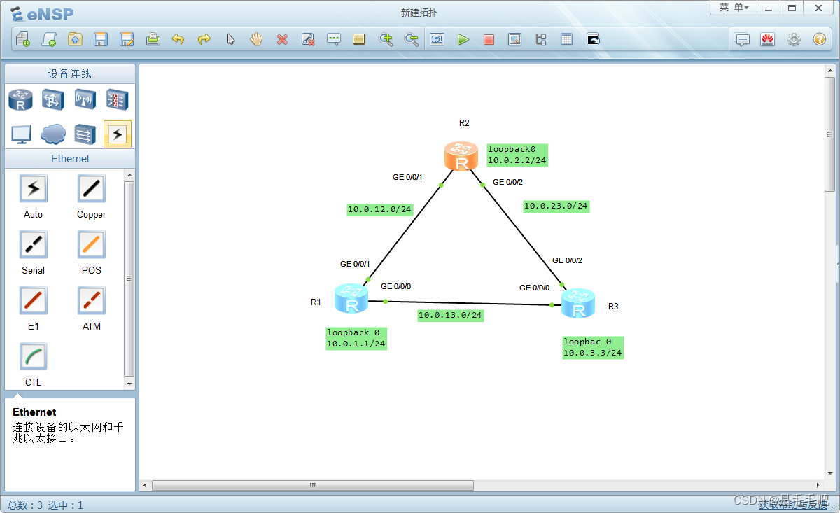
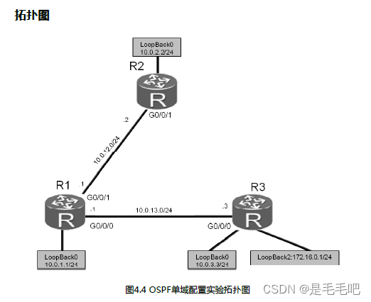
2.OSPF路由协议的配置步骤:
拓扑图
您是公司的网络管理员。现在公司网络中需要使用OSPF协议来进行路由信息的传递。觃划网络中所有路由器属于OSPF的区域0。实际使用中需要向OSPF发布默认路由,此外您也希望通过这次部署了解DR/BDR选丼的机制。
操作步骤
.步骤一 实验环境准备
如果本任务中您使用的是空配置设备,需要从步骤1开始配置,然后跳过步骤2。如果使用的设备包含上一个实验的配置,请直接从步骤2开始配置。
基本配置以及IP编址。
<Huawei>system
Enter system view, return user view with Ctrl+Z.
[Huawei]sysname R1
[R1]int G 0/0/1
[R1-GigabitEthernet 0/0/1]ip add 10.0.12.1 24
[R1-GigabitEthernet 0/0/1]quit
[R1]int G 0/0/0
[R1-GigabitEthernet0/0/0]ip add 10.0.13.1 24
[R1-GigabitEthernet0/0/0]quit
[R1]int LoopBack 0
[R1-LoopBack0]ip add 10.0.1.1 24
<Huawei>system
Enter system view, return user view with Ctrl+Z.
[Huawei]sysname R2
[R2]int G 0/0/1
[R2-GigabitEthernet 0/0/1]ip add 10.0.12.2 24
[R2-GigabitEthernet 0/0/1]quit
[R2]int LoopBack 0
[R2-LoopBack0]ip add 10.0.2.2 24
<Huawei>system
Enter system view, return user view with Ctrl+Z.
[Huawei]sysname R3
[R3]int G 0/0/0
[R3-GigabitEthernet0/0/0]ip add 10.0.13.3 24
[R3-GigabitEthernet0/0/0]quit
[R3]int LoopBack 0
[R3-LoopBack0]ip add 10.0.3.3 24
[R3-LoopBack0]quit
[R3]int LoopBack 2
[R3-LoopBack2]ip add 172.16.0.1 24
.步骤二 配置OSPF
将R1的Router ID配置为10.0.1.1(逻辑接口Loopback 0的地址),开启OSPF进程1(缺省进程),并将网段10.0.1.0/24、10.0.12.0/24和10.0.13.0/24发布到OSPF区域0。
[R1]ospf 1 router-id 10.0.1.1
[R1-ospf-1]area 0
[R1-ospf-1-area-0.0.0.0]network 10.0.1.0 0.0.0.255
[R1-ospf-1-area-0.0.0.0]network 10.0.13.0 0.0.0.255
[R1-ospf-1-area-0.0.0.0]network 10.0.12.0 0.0.0.255
注意:同一个路由器可以开启多个OSPF进程,默认进程号为1,由于进程号只具有本地意义,所以同一路由域的不同路由器可以使用相同或不同的OSPF进程号。另外network命令后面需使用反掩码。
将R2的Router ID配置为10.0.2.2,开启OSPF进程1,并将网段10.0.12.0/24和10.0.2.0/24发布到OSPF区域0。 area 0 骨干区域
[R2]ospf 1 router-id 10.0.2.2
[R2-ospf-1]area 0 //骨干域
[R2-ospf-1-area-0.0.0.0]network 10.0.2.0 0.0.0.255
[R2-ospf-1-area-0.0.0.0]network 10.0.12.0 0.0.0.255
…output omitted…
Nov 30 2013 09:41:39+00:00 R2 %%01OSPF/4/NBR_CHANGE_E(l)[5]:Neighbor changes event: neighbor status changed. (ProcessId=1, NeighborAddress=10.0.12.1, NeighborEvent=LoadingDone, NeighborPreviousState=Loading, NeighborCurrentState=Full)
当回显信息中包含“NeighborCurrentState=Full”信息时,表明邻接关系已绉建立。
将R3的Router ID配置为10.0.3.3,开启OSPF进程1,并将网段10.0.3.0/24和10.0.13.0/24发布到OSPF区域0。
[R3]ospf 1 router-id 10.0.3.3
[R3-ospf-1]area 0
[R3-ospf-1-area-0.0.0.0]network 10.0.3.0 0.0.0.255
[R3-ospf-1-area-0.0.0.0]network 10.0.13.0 0.0.0.255
…output omitted…
Nov 30 2013 16:05:34+00:00 R3 %%01OSPF/4/NBR_CHANGE_E(l)[5]:Neighbor changes event: neighbor status changed. (ProcessId=1, NeighborAddress=10.0.13.1, NeighborEvent=LoadingDone, NeighborPreviousState=Loading, NeighborCurrentState=Full)
.步骤四 验证OSPF配置
待OSPF收敛完成后,查看R1、R2和R3上的路由表。
<R1>dis ip routing-table
Route Flags: R - relay, D - download to fib
Routing Tables: Public
Destinations : 15 Routes : 15
Destination/Mask Proto Pre Cost Flags NextHop Interface
10.0.1.0/24 Direct 0 0 D 10.0.1.1 LoopBack0
10.0.1.1/32 Direct 0 0 D 127.0.0.1 LoopBack0
10.0.1.255/32 Direct 0 0 D 127.0.0.1 LoopBack0
10.0.2.2/32 OSPF 10 1 D 10.0.12.2 GigabitEthernet0/0/1
10.0.3.3/32 OSPF 10 1 D 10.0.13.3 GigabitEthernet0/0/0
10.0.12.0/24 Direct 0 0 D 10.0.12.1 GigabitEthernet0/0/1
10.0.12.1/32 Direct 0 0 D 127.0.0.1 GigabitEthernet0/0/1
10.0.12.255/32 Direct 0 0 D 127.0.0.1 GigabitEthernet0/0/1
10.0.13.0/24 Direct 0 0 D 10.0.13.1 GigabitEthernet0/0/0
10.0.13.1/32 Direct 0 0 D 127.0.0.1 GigabitEthernet0/0/0
10.0.13.255/32 Direct 0 0 D 127.0.0.1 GigabitEthernet0/0/0
127.0.0.0/8 Direct 0 0 D 127.0.0.1 InLoopBack0
127.0.0.1/32 Direct 0 0 D 127.0.0.1 InLoopBack0
127.255.255.255/32 Direct 0 0 D 127.0.0.1 InLoopBack0
255.255.255.255/32 Direct 0 0 D 127.0.0.1 InLoopBack0
<R2>display ip routing-table
Route Flags: R - relay, D - download to fib
Routing Tables: Public
Destinations : 13 Routes : 13
Destination/Mask Proto Pre Cost Flags NextHop Interface
10.0.1.1/32 OSPF 10 1 D 10.0.12.1 GigabitEthernet0/0/1
10.0.2.0/24 Direct 0 0 D 10.0.2.2 LoopBack0
10.0.2.2/32 Direct 0 0 D 127.0.0.1 LoopBack0
10.0.2.255/32 Direct 0 0 D 127.0.0.1 LoopBack0
10.0.3.3/32 OSPF 10 2 D 10.0.12.1 GigabitEthernet0/0/1
10.0.12.0/24 Direct 0 0 D 10.0.12.2 GigabitEthernet0/0/1
10.0.12.2/32 Direct 0 0 D 127.0.0.1 GigabitEthernet0/0/1
10.0.12.255/32 Direct 0 0 D 127.0.0.1 GigabitEthernet0/0/1
10.0.13.0/24 OSPF 10 2 D 10.0.12.1 GigabitEthernet0/0/1
127.0.0.0/8 Direct 0 0 D 127.0.0.1 InLoopBack0
127.0.0.1/32 Direct 0 0 D 127.0.0.1 InLoopBack0
127.255.255.255/32 Direct 0 0 D 127.0.0.1 InLoopBack0
255.255.255.255/32 Direct 0 0 D 127.0.0.1 InLoopBack0
<R3>display ip routing-table
Route Flags: R - relay, D - download to fib
Routing Tables: Public
Destinations : 16 Routes : 16
Destination/Mask Proto Pre Cost Flags NextHop Interface
10.0.1.1/32 OSPF 10 1 D 10.0.13.1 GigabitEthernet0/0/0
10.0.2.2/32 OSPF 10 2 D 10.0.13.1 GigabitEthernet0/0/0
10.0.3.0/24 Direct 0 0 D 10.0.3.3 LoopBack0
10.0.3.3/32 Direct 0 0 D 127.0.0.1 LoopBack0
10.0.3.255/32 Direct 0 0 D 127.0.0.1 LoopBack0
10.0.12.0/24 OSPF 10 2 D 10.0.13.1 GigabitEthernet0/0/0
10.0.13.0/24 Direct 0 0 D 10.0.13.3 GigabitEthernet0/0/0
10.0.13.3/32 Direct 0 0 D 127.0.0.1 GigabitEthernet0/0/0
10.0.13.255/32 Direct 0 0 D 127.0.0.1 GigabitEthernet0/0/0
127.0.0.0/8 Direct 0 0 D 127.0.0.1 InLoopBack0
127.0.0.1/32 Direct 0 0 D 127.0.0.1 InLoopBack0
127.255.255.255/32 Direct 0 0 D 127.0.0.1 InLoopBack0
172.16.0.0/24 Direct 0 0 D 172.16.0.1 LoopBack2
172.16.0.1/32 Direct 0 0 D 127.0.0.1 LoopBack2
172.16.0.255/32 Direct 0 0 D 127.0.0.1 LoopBack2
255.255.255.255/32 Direct 0 0 D 127.0.0.1 InLoopBack0
检测R2和R1(10.0.1.1)以及R2和R3(10.0.3.3)间的连通性。
<R2>ping 10.0.1.1
PING 10.0.1.1: 56 data bytes, press CTRL_C to break
Reply from 10.0.1.1: bytes=56 Sequence=1 ttl=255 time=37 ms
Reply from 10.0.1.1: bytes=56 Sequence=2 ttl=255 time=42 ms
Reply from 10.0.1.1: bytes=56 Sequence=3 ttl=255 time=42 ms
Reply from 10.0.1.1: bytes=56 Sequence=4 ttl=255 time=45 ms
Reply from 10.0.1.1: bytes=56 Sequence=5 ttl=255 time=42 ms
--- 10.0.1.1 ping statistics ---
5 packet(s) transmitted
5 packet(s) received
0.00% packet loss
round-trip min/avg/max = 37/41/45 ms
<R2>ping 10.0.3.3
PING 10.0.3.3: 56 data bytes, press CTRL_C to break
Reply from 10.0.3.3: bytes=56 Sequence=1 ttl=254 time=37 ms
Reply from 10.0.3.3: bytes=56 Sequence=2 ttl=254 time=42 ms
Reply from 10.0.3.3: bytes=56 Sequence=3 ttl=254 time=42 ms
Reply from 10.0.3.3: bytes=56 Sequence=4 ttl=254 time=42 ms
Reply from 10.0.3.3: bytes=56 Sequence=5 ttl=254 time=42 ms
--- 10.0.3.3 ping statistics ---
5 packet(s) transmitted
5 packet(s) received
0.00% packet loss
round-trip min/avg/max = 37/41/42 ms
执行display ospf peer命令,查看OSPF邻居状态。
<R1>dis ospf peer
OSPF Process 1 with Router ID 10.0.1.1
Neighbors
Area 0.0.0.0 interface 10.0.12.1(GigabitEthernet0/0/1)'s neighbors
Router ID: 10.0.2.2 Address: 10.0.12.2
State: Full Mode:Nbr is Master Priority: 1
DR: 10.0.12.1 BDR: 10.0.12.2 MTU: 0
Dead timer due in 32 sec
Retrans timer interval: 5
Neighbor is up for 00:47:59
Authentication Sequence: [ 0 ]
Neighbors
Area 0.0.0.0 interface 10.0.13.1(GigabitEthernet0/0/0)'s neighbors
Router ID: 10.0.3.3 Address: 10.0.13.3
State: Full Mode:Nbr is Master Priority: 1
DR: 10.0.13.1 BDR: 10.0.13.3 MTU: 0
Dead timer due in 34 sec
Retrans timer interval: 5
Neighbor is up for 00:41:44
Authentication Sequence: [ 0 ]
display ospf peer命令显示所有OSPF邻居的详细信息。本任务中,10.0.13.0网段上R1是DR。由于DR选丼是非抢占模式,如果OSPF进程不重启,R3将不会取代R1的DR角色。
执行display ospf peer brief命令,可以查看简要的OSPF邻居信息。
<R1>display ospf peer brief
OSPF Process 1 with Router ID 10.0.1.1
Peer Statistic Information
Area Id Interface Neighbor id State
0.0.0.0 GigabitEthernet0/0/0 10.0.3.3 Full
0.0.0.0 GigabitEthernet0/0/1 10.0.2.2 Full
<R2>display ospf peer brief
OSPF Process 1 with Router ID 10.0.2.2
Peer Statistic Information
Area Id Interface Neighbor id State
0.0.0.0 GigabitEthernet0/0/1 10.0.1.1 Full
<R3>display ospf peer brief
OSPF Process 1 with Router ID 10.0.3.3
Peer Statistic Information
Area Id Interface Neighbor id State
0.0.0.0 GigabitEthernet0/0/0 10.0.1.1 Full
.步骤五 修改OSPF hello和dead时间参数
在R1上执行display ospf interface GigabitEthernet 0/0/0命令,查看OSPF默认的hello和dead时间。
<R1>display ospf interface GigabitEthernet 0/0/0
OSPF Process 1 with Router ID 10.0.1.1
Interfaces
Interface: 10.0.13.1 (GigabitEthernet0/0/0)
Cost: 1 State: DR Type: Broadcast MTU: 1500
Priority: 1
Designated Router: 10.0.13.1
Backup Designated Router: 10.0.13.3
Timers: Hello 10 , Dead 40 , Poll 120 , Retransmit 5 , Transmit Delay 1
在R1的GE0/0/0接口执行ospf timer命令,将OSPF hello和dead时间分别修改为15秒和60秒。
[R1]interface GigabitEthernet 0/0/0
[R1-GigabitEthernet0/0/0]ospf timer hello 15
[R1-GigabitEthernet0/0/0]ospf timer dead 60
Nov 30 2013 16:58:39+00:00 R1 %%01OSPF/3/NBR_DOWN_REASON(l)[1]:Neighbor state leaves full or changed to Down. (ProcessId=1, NeighborRouterId=10.0.3.3, NeighborAreaId=0, NeighborInterface=GigabitEthernet0/0/0,NeighborDownImmediate
reason=Neighbor Down Due to Inactivity, NeighborDownPrimeReason=Interface Parameter Mismatch, NeighborChangeTime=2013-11-30 16:58:39)
<R1>display ospf interface GigabitEthernet 0/0/0
OSPF Process 1 with Router ID 10.0.1.1
Interfaces
Interface: 10.0.13.1 (GigabitEthernet0/0/0)
Cost: 1 State: DR Type: Broadcast MTU: 1500
Priority: 1
Designated Router: 10.0.13.1
Backup Designated Router: 10.0.13.3
Timers: Hello 15 , Dead 60 , Poll 120 , Retransmit 5 , Transmit Delay 1
在R1上查看OSPF邻居状态。
<R1>display ospf peer brief
OSPF Process 1 with Router ID 10.0.1.1
Peer Statistic Information
-------------------------------------------------------------------------
Area Id Interface Neighbor id State
0.0.0.0 GigabitEthernet0/0/1 10.0.2.2 Full
-------------------------------------------------------------------------
上述回显信息表明,R1只有一个邻居,那就是R2。因为R1和R3上的OSPF hello和dead时间取值不同,所以R1无法不R3建立OSPF邻居关系。
在R3的GE0/0/0接口执行ospf timer命令,将OSPF hello和dead时间分别修改为15秒和60秒。
[R3]interface GigabitEthernet 0/0/0
[R3-GigabitEthernet0/0/0]ospf timer hello 15
[R3-GigabitEthernet0/0/0]ospf timer dead 60
…output omitted…
Nov 30 2013 17:03:33+00:00 R3 %%01OSPF/4/NBR_CHANGE_E(l)[4]:Neighbor changes event: neighbor status changed. (ProcessId=1, NeighborAddress=10.0.13.1, NeighborEvent=LoadingDone, NeighborPreviousState=Loading, NeighborCurrentState=Full)
<R3>display ospf interface GigabitEthernet 0/0/0
OSPF Process 1 with Router ID 10.0.3.3
Interfaces
Interface: 10.0.13.3 (GigabitEthernet0/0/0)
Cost: 1 State: DR Type: Broadcast MTU: 1500
Priority: 1
Designated Router: 10.0.13.3
Backup Designated Router: 10.0.13.1
Timers: Hello 15 , Dead 60 , Poll 120 , Retransmit 5 , Transmit Delay 1
再次在R1上查看OSPF邻居状态。
<R1>display ospf peer brief
OSPF Process 1 with Router ID 10.0.1.1
Peer Statistic Information
------------------------------------------------------------------------
Area Id Interface Neighbor id State
0.0.0.0 GigabitEthernet0/0/0 10.0.3.3 Full
0.0.0.0 GigabitEthernet0/0/1 10.0.2.2 Full
-------------------------------------------------------------------------
.步骤六 OSPF缺省路由发布及验证
在R3上配置缺省路由并发布到OSPF域内。 LoopBack本地环回接口(或地址),
[R3]ip route-static 0.0.0.0 0.0.0.0 LoopBack 2
[R3]ospf 1
[R3-ospf-1]default-route-advertise //本路由器发布一条0.0.0.0/0.0.0.0的路由到域内其他路由器
查看R1和R2的路由表。可以看到,R1和R2均已绉学习到了R3发布的缺省路由。
<R1>display ip routing-table
Route Flags: R - relay, D - download to fib
-------------------------------------------------------------------------
Routing Tables: Public
Destinations : 16 Routes : 16
Destination/Mask Proto Pre Cost Flags NextHop Interface
0.0.0.0/0 O_ASE 150 1 D 10.0.13.3 GigabitEthernet0/0/0
10.0.1.0/24 Direct 0 0 D 10.0.1.1 LoopBack0
10.0.1.1/32 Direct 0 0 D 127.0.0.1 LoopBack0
10.0.1.255/32 Direct 0 0 D 127.0.0.1 LoopBack0
10.0.2.2/32 OSPF 10 1 D 10.0.12.2 GigabitEthernet0/0/1
10.0.3.3/32 OSPF 10 1 D 10.0.13.3 GigabitEthernet0/0/0
10.0.12.0/24 Direct 0 0 D 10.0.12.1 GigabitEthernet0/0/1
10.0.12.1/32 Direct 0 0 D 127.0.0.1 GigabitEthernet0/0/1
10.0.12.255/32 Direct 0 0 D 127.0.0.1 GigabitEthernet0/0/1
10.0.13.0/24 Direct 0 0 D 10.0.13.1 GigabitEthernet0/0/0
10.0.13.1/32 Direct 0 0 D 127.0.0.1 GigabitEthernet0/0/0
10.0.13.255/32 Direct 0 0 D 127.0.0.1 GigabitEthernet0/0/0
127.0.0.0/8 Direct 0 0 D 127.0.0.1 InLoopBack0
127.0.0.1/32 Direct 0 0 D 127.0.0.1 InLoopBack0
127.255.255.255/32 Direct 0 0 D 127.0.0.1 InLoopBack0
255.255.255.255/32 Direct 0 0 D 127.0.0.1 InLoopBack0
<R2>display ip routing-table
Route Flags: R - relay, D - download to fib
-------------------------------------------------------------------------
Routing Tables: Public
Destinations : 14 Routes : 14
Destination/Mask Proto Pre Cost Flags NextHop Interface
0.0.0.0/0 O_ASE 150 1 D 10.0.12.1 GigabitEthernet0/0/1
10.0.1.1/32 OSPF1 0 1 D 10.0.12.1 GigabitEthernet0/0/1
10.0.2.0/24 Direct 0 0 D 10.0.2.2 LoopBack0
10.0.2.2/32 Direct 0 0 D 127.0.0.1 LoopBack0
10.0.2.255/32 Direct 0 0 D 127.0.0.1 LoopBack0
10.0.3.3/32 OSPF 10 2 D 10.0.12.1 GigabitEthernet0/0/1
10.0.12.0/24 Direct 0 0 D 10.0.12.2 GigabitEthernet0/0/1
10.0.12.2/32 Direct 0 0 D 127.0.0.1 GigabitEthernet0/0/1
10.0.12.255/32 Direct 0 0 D 127.0.0.1 GigabitEthernet0/0/1
10.0.13.0/24 OSPF 10 2 D 10.0.12.1 GigabitEthernet0/0/1
127.0.0.0/8 Direct 0 0 D 127.0.0.1 InLoopBack0
127.0.0.1/32 Direct 0 0 D 127.0.0.1 InLoopBack0
127.255.255.255/32 Direct 0 0 D 127.0.0.1 InLoopBack0
255.255.255.255/32 Direct 0 0 D 127.0.0.1 InLoopBack0
<R3>display ip routing-table
Route Flags: R - relay, D - download to fib
-------------------------------------------------------------
Routing Tables: Public
Destinations : 17 Routes : 17
Destination/Mask Proto Pre Cost Flags NextHop Interface
0.0.0.0/0 Static 60 0 D 172.16.0.1 LoopBack2
10.0.1.1/32 OSPF 10 1 D 10.0.13.1 GigabitEthernet0/0/0
10.0.2.2/32 OSPF 10 2 D 10.0.13.1 GigabitEthernet0/0/0
10.0.3.0/24 Direct 0 0 D 10.0.3.3 LoopBack0
10.0.3.3/32 Direct 0 0 D 127.0.0.1 LoopBack0
10.0.3.255/32 Direct 0 0 D 127.0.0.1 LoopBack0
10.0.12.0/24 OSPF 10 2 D 10.0.13.1 GigabitEthernet0/0/0
10.0.13.0/24 Direct 0 0 D 10.0.13.3 GigabitEthernet0/0/0
10.0.13.3/32 Direct 0 0 D 127.0.0.1 GigabitEthernet0/0/0
10.0.13.255/32 Direct 0 0 D 127.0.0.1 GigabitEthernet0/0/0
127.0.0.0/8 Direct 0 0 D 127.0.0.1 InLoopBack0
127.0.0.1/32 Direct 0 0 D 127.0.0.1 InLoopBack0
127.255.255.255/32 Direct 0 0 D 127.0.0.1 InLoopBack0
172.16.0.0/24 Direct 0 0 D 172.16.0.1 LoopBack2
172.16.0.1/32 Direct 0 0 D 127.0.0.1 LoopBack2
172.16.0.255/32 Direct0 0 D 127.0.0.1 LoopBack2
255.255.255.255/32 Direct0 0 D 127.0.0.1 InLoopBack0
使用ping命令,检测R2不172.16.0.1/24网段之间的连通性。
<R2>ping 172.16.0.1
PING 172.16.0.1: 56 data bytes, press CTRL_C to break
Reply from 172.16.0.1: bytes=56 Sequence=1 ttl=254 time=47 ms
Reply from 172.16.0.1: bytes=56 Sequence=2 ttl=254 time=37 ms
Reply from 172.16.0.1: bytes=56 Sequence=3 ttl=254 time=37 ms
Reply from 172.16.0.1: bytes=56 Sequence=4 ttl=254 time=37 ms
Reply from 172.16.0.1: bytes=56 Sequence=5 ttl=254 time=37 ms
--- 172.16.0.1 ping statistics ---
5 packet(s) transmitted
5 packet(s) received
0.00% packet loss
round-trip min/avg/max = 37/39/47 ms
.步骤七 控制OSPF DR/BDR的选举
执行display ospf peer命令,查看R1和R3的DR/BDR角色。
<R1>display ospf peer 10.0.3.3
OSPF Process 1 with Router ID 10.0.1.1
Neighbors
Area 0.0.0.0 interface 10.0.13.1(GigabitEthernet0/0/0)'s neighbors
Router ID: 10.0.3.3 Address: 10.0.13.3
State: Full Mode:Nbr is Master Priority: 1
DR: 10.0.13.3 BDR: 10.0.13.1 MTU: 0
Dead timer due in 49 sec
Retrans timer interval: 5
Neighbor is up for 00:17:40
Authentication Sequence: [ 0 ]
上述回显信息表明,由于默认路由器优先级(数值为1)相同,但R3的Router ID 10.0.3.3大于R1的Router ID 10.0.1.1,所以R3为DR,R1为BDR。
执行ospf dr-priority命令,修改R1和R3的DR优先级。
[R1]interface GigabitEthernet 0/0/0
[R1-GigabitEthernet0/0/0]ospf dr-priority 200
[R3]interface GigabitEthernet 0/0/0
[R3-GigabitEthernet0/0/0]ospf dr-priority 100
默认情况下,DR/BDR的选丼采用的是非抢占模式。路由器优先级修改后,不会自劢重新选丼DR。因此,需要重置R1和R3间的OSPF邻居关系。
先关闭然后再打开R1和R3上的Gigabit Ethernet 0/0/0接口,重置R1和R3间的OSPF邻居关系。
[R3]interface GigabitEthernet0/0/0
[R3-GigabitEthernet0/0/0]shutdown
[R1]interface GigabitEthernet0/0/0
[R1-GigabitEthernet0/0/0]shutdown //关闭
[R1-GigabitEthernet0/0/0]undo shutdown //用来开启当前接口
[R3-GigabitEthernet0/0/0]undo shutdown
执行display ospf peer命令,查看R1和R3的DR/BDR角色。
[R1]display ospf peer 10.0.3.3
OSPF Process 1 with Router ID 10.0.1.1
Neighbors
Area 0.0.0.0 interface 10.0.13.1(GigabitEthernet0/0/0)'s neighbors
Router ID: 10.0.3.3 Address: 10.0.13.3
State: Full Mode:Nbr is Master Priority: 100
DR: 10.0.13.1 BDR: 10.0.13.3 MTU: 0
Dead timer due in 52 sec
Retrans timer interval: 5
Neighbor is up for 00:00:25
Authentication Sequence: [ 0 ]
上述信息表明,R1的DR优先级高于R3,因此R1被选丼为DR,而R3成为了BDR。
配置文件
<R1>display current-configuration
[V200R003C00SPC200]
#
sysname R1
#
interface GigabitEthernet0/0/0
ip address 10.0.13.1 255.255.255.0
ospf dr-priority 200
ospf timer hello 15
#
interface GigabitEthernet0/0/1
ip address 10.0.12.1 255.255.255.0
#
interface LoopBack0
ip address 10.0.1.1 255.255.255.0
#
ospf 1 router-id 10.0.1.1
area 0.0.0.0
network 10.0.1.0 0.0.0.255
network 10.0.12.0 0.0.0.255
network 10.0.13.0 0.0.0.255
#
user-interface con 0
authentication-mode password
set authentication password cipher %$%$+L'YR&IZt'4,)>-*#lH",}%K-oJ_M9+'lOU~bD (\WTqB}%N,%$%$
user-interface vty 0 4
#
return
<R2>display current-configuration
[V200R003C00SPC200]
#
sysname R2
#
interface GigabitEthernet0/0/1
ip address 10.0.12.2 255.255.255.0
#
interface LoopBack0
ip address 10.0.2.2 255.255.255.0
#
ospf 1 router-id 10.0.2.2
area 0.0.0.0
network 10.0.2.0 0.0.0.255
network 10.0.12.0 0.0.0.255
#
user-interface con 0
authentication-mode password
set authentication password cipher %$%$1=cd%b%/O%Id-8X:by1N,+s}'4wD6TvO<I|/pd# #44C@+s#,%$%$
user-interface vty 0 4
#
return
<R3>display current-configuration
[V200R003C00SPC200]
#
sysname R3
#
interface GigabitEthernet0/0/0
ip address 10.0.13.3 255.255.255.0
ospf dr-priority 100
ospf timer hello 15
#
interface LoopBack0
ip address 10.0.3.3 255.255.255.0
#
interface LoopBack2
ip address 172.16.0.1 255.255.255.0
#
ospf 1 router-id 10.0.3.3
default-route-advertise
area 0.0.0.0
network 10.0.3.0 0.0.0.255
network 10.0.13.0 0.0.0.255
#
ip route-static 0.0.0.0 0.0.0.0 LoopBack2
#
user-interface con 0
authentication-mode password
set authentication password cipher %$%$ksXDMg7Ry6yUU:63:DQ),#/sQg"@*S\U#.s.bHW xQ,y%#/v,%$%$
user-interface vty 0 4
#
return
五、实验结果:
能完成简单路由器协议配置过程。


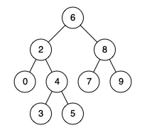

![[技术杂谈]如何下载vscode历史版本](https://img-blog.csdnimg.cn/direct/18e927e78e82496e80649940eb70a716.png)