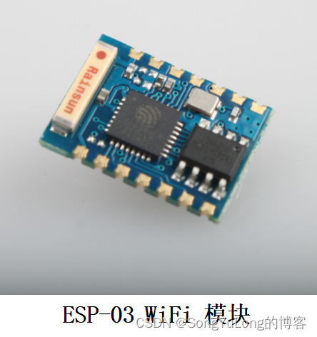
ESP8266模块
模块实物图:
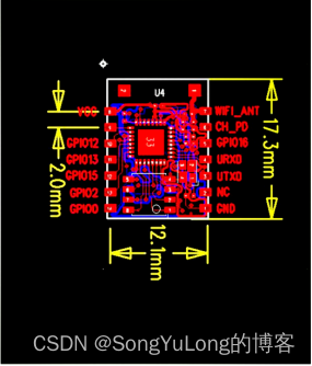
模块引脚定义:
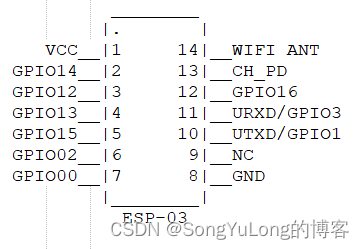
工作模式选择:
-
FlashBoot启动模式:
GPIO15接GND -
UART固件下载模式:
GPIO15接GND, GPIO0接GND -
调试串口:
URXD/UTXD 可用来下载固件和调试信息输出 -
模块使能:
CH_DP接高电平模块上电,接低电平模块掉电
模块上电默认波特率74880
第一行打印boot mode:(1,x) 已经进入下载模式
ets Jan 8 2013,rst cause:1, boot mode:(1,6)
FlashBoot mode:
第一行打印ets Jan 8 2013,rst cause:1, boot mode:(3,6)
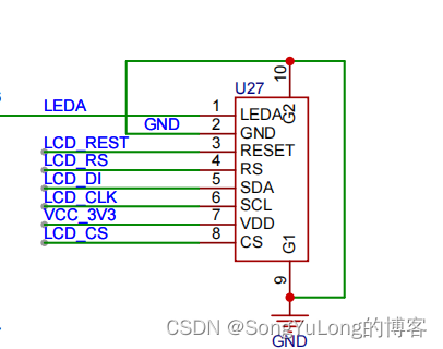
显示屏引脚定义:
0.96inch,TFT彩屏,分辨率:160x80, ST7735驱动
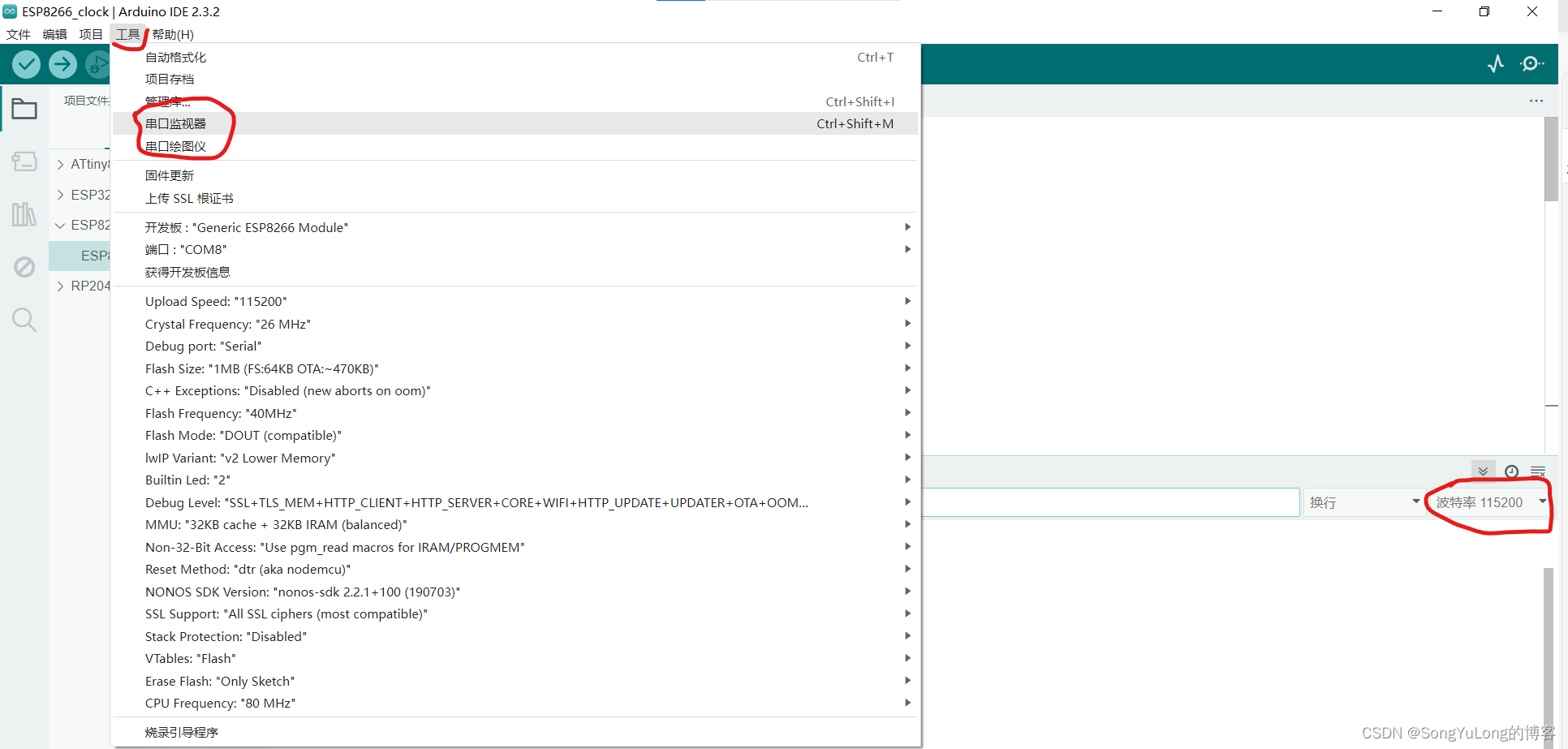
Arduino启动串口工具
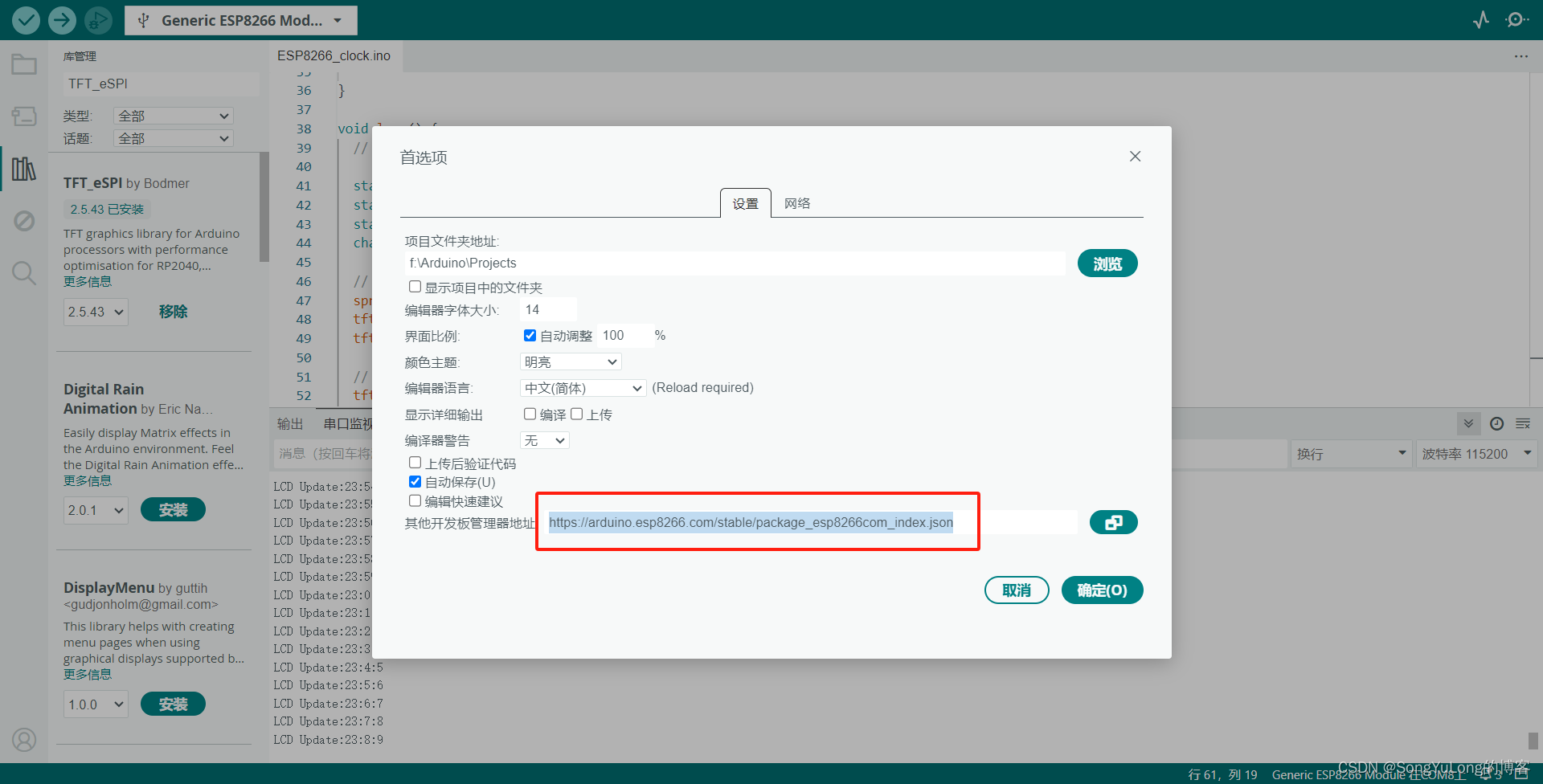
Arduino ESP8266安装包
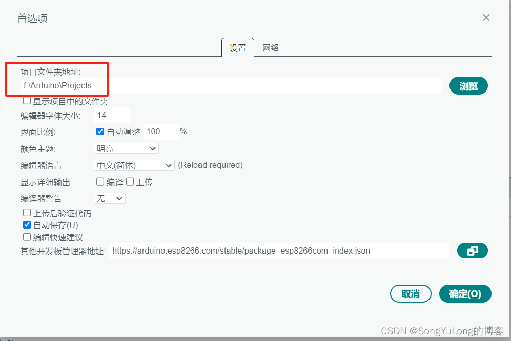
文件=》首选项=》其他开发板管理器地址:
https://arduino.esp8266.com/stable/package_esp8266com_index.json
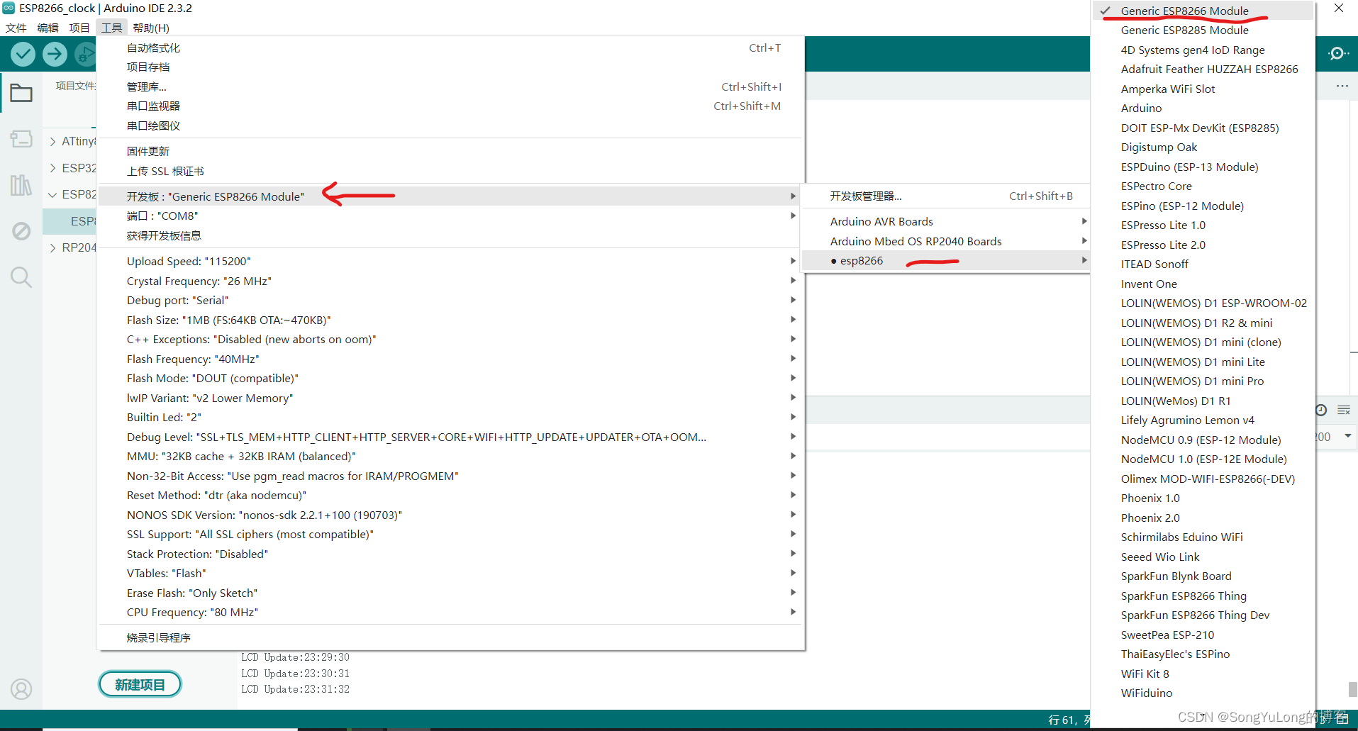
选择开发板
工具=》开发板=》esp8266=>Generic ESP8266 Module
(根据实际开发板型号选择,本文选择通用模块)
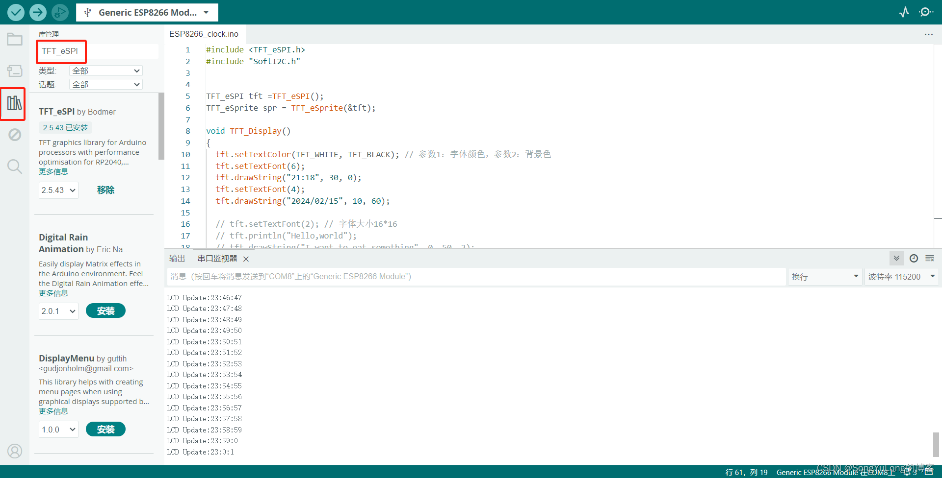
安装TFT_eSPI库
库管理=》搜索TFT_eSPI 点击《安装》按钮即可安装
修改TFT_eSPI配置文件
打开项目文件下libraries/TFT_eSPI/User_Setup.h根据实际需要修改配置
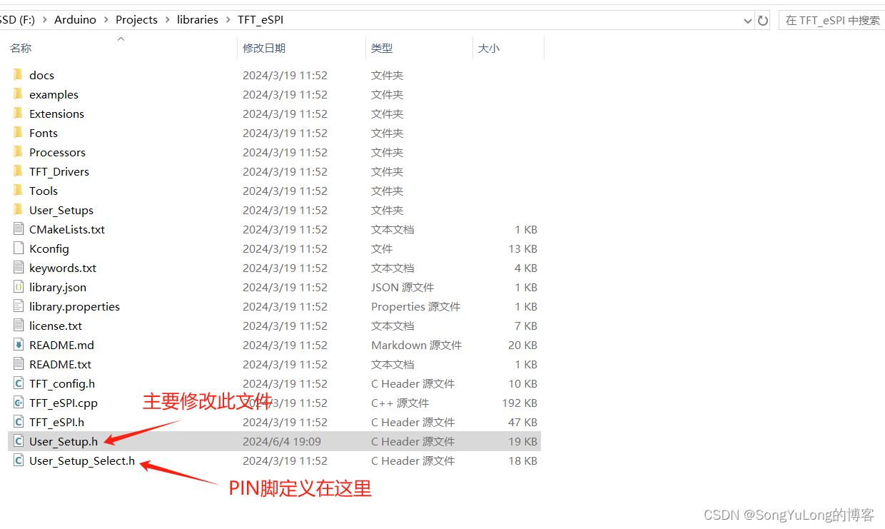
本例修改如下:
//                            USER DEFINED SETTINGS
//   Set driver type, fonts to be loaded, pins used and SPI control method etc.
//
//   See the User_Setup_Select.h file if you wish to be able to define multiple
//   setups and then easily select which setup file is used by the compiler.
//
//   If this file is edited correctly then all the library example sketches should
//   run without the need to make any more changes for a particular hardware setup!
//   Note that some sketches are designed for a particular TFT pixel width/height// User defined information reported by "Read_User_Setup" test & diagnostics example
#define USER_SETUP_INFO "User_Setup"// Define to disable all #warnings in library (can be put in User_Setup_Select.h)
//#define DISABLE_ALL_LIBRARY_WARNINGS// ##################################################################################
//
// Section 1. Call up the right driver file and any options for it
//
// ##################################################################################// Define STM32 to invoke optimised processor support (only for STM32)
//#define STM32// Defining the STM32 board allows the library to optimise the performance
// for UNO compatible "MCUfriend" style shields
//#define NUCLEO_64_TFT
//#define NUCLEO_144_TFT// STM32 8-bit parallel only:
// If STN32 Port A or B pins 0-7 are used for 8-bit parallel data bus bits 0-7
// then this will improve rendering performance by a factor of ~8x
//#define STM_PORTA_DATA_BUS
//#define STM_PORTB_DATA_BUS// Tell the library to use parallel mode (otherwise SPI is assumed)
//#define TFT_PARALLEL_8_BIT
//#defined TFT_PARALLEL_16_BIT // **** 16-bit parallel ONLY for RP2040 processor ****// Display type -  only define if RPi display
//#define RPI_DISPLAY_TYPE // 20MHz maximum SPI// Only define one driver, the other ones must be commented out
//#define ILI9341_DRIVER       // Generic driver for common displays
//#define ILI9341_2_DRIVER     // Alternative ILI9341 driver, see https://github.com/Bodmer/TFT_eSPI/issues/1172
#define ST7735_DRIVER      // Define additional parameters below for this display
//#define ILI9163_DRIVER     // Define additional parameters below for this display
//#define S6D02A1_DRIVER
//#define RPI_ILI9486_DRIVER // 20MHz maximum SPI
//#define HX8357D_DRIVER
//#define ILI9481_DRIVER
//#define ILI9486_DRIVER
//#define ILI9488_DRIVER     // WARNING: Do not connect ILI9488 display SDO to MISO if other devices share the SPI bus (TFT SDO does NOT tristate when CS is high)
//#define ST7789_DRIVER      // Full configuration option, define additional parameters below for this display
//#define ST7789_2_DRIVER    // Minimal configuration option, define additional parameters below for this display
//#define R61581_DRIVER
//#define RM68140_DRIVER
//#define ST7796_DRIVER
//#define SSD1351_DRIVER
//#define SSD1963_480_DRIVER
//#define SSD1963_800_DRIVER
//#define SSD1963_800ALT_DRIVER
//#define ILI9225_DRIVER
//#define GC9A01_DRIVER// Some displays support SPI reads via the MISO pin, other displays have a single
// bi-directional SDA pin and the library will try to read this via the MOSI line.
// To use the SDA line for reading data from the TFT uncomment the following line:// #define TFT_SDA_READ      // This option is for ESP32 ONLY, tested with ST7789 and GC9A01 display only// For ST7735, ST7789 and ILI9341 ONLY, define the colour order IF the blue and red are swapped on your display
// Try ONE option at a time to find the correct colour order for your display//  #define TFT_RGB_ORDER TFT_RGB  // Colour order Red-Green-Blue
//  #define TFT_RGB_ORDER TFT_BGR  // Colour order Blue-Green-Red// For M5Stack ESP32 module with integrated ILI9341 display ONLY, remove // in line below// #define M5STACK// For ST7789, ST7735, ILI9163 and GC9A01 ONLY, define the pixel width and height in portrait orientation
#define TFT_WIDTH  80
// #define TFT_WIDTH  128
// #define TFT_WIDTH  172 // ST7789 172 x 320
// #define TFT_WIDTH  170 // ST7789 170 x 320
// #define TFT_WIDTH  240 // ST7789 240 x 240 and 240 x 320
#define TFT_HEIGHT 160
// #define TFT_HEIGHT 128
// #define TFT_HEIGHT 240 // ST7789 240 x 240
// #define TFT_HEIGHT 320 // ST7789 240 x 320
// #define TFT_HEIGHT 240 // GC9A01 240 x 240// For ST7735 ONLY, define the type of display, originally this was based on the
// colour of the tab on the screen protector film but this is not always true, so try
// out the different options below if the screen does not display graphics correctly,
// e.g. colours wrong, mirror images, or stray pixels at the edges.
// Comment out ALL BUT ONE of these options for a ST7735 display driver, save this
// this User_Setup file, then rebuild and upload the sketch to the board again:// #define ST7735_INITB
// #define ST7735_GREENTAB
// #define ST7735_GREENTAB2
// #define ST7735_GREENTAB3
// #define ST7735_GREENTAB128    // For 128 x 128 display
#define ST7735_GREENTAB160x80 // For 160 x 80 display (BGR, inverted, 26 offset)
// #define ST7735_ROBOTLCD       // For some RobotLCD Arduino shields (128x160, BGR, https://docs.arduino.cc/retired/getting-started-guides/TFT)
// #define ST7735_REDTAB
// #define ST7735_BLACKTAB
// #define ST7735_REDTAB160x80   // For 160 x 80 display with 24 pixel offset// If colours are inverted (white shows as black) then uncomment one of the next
// 2 lines try both options, one of the options should correct the inversion.// #define TFT_INVERSION_ON
// #define TFT_INVERSION_OFF// ##################################################################################
//
// Section 2. Define the pins that are used to interface with the display here
//
// ##################################################################################// If a backlight control signal is available then define the TFT_BL pin in Section 2
// below. The backlight will be turned ON when tft.begin() is called, but the library
// needs to know if the LEDs are ON with the pin HIGH or LOW. If the LEDs are to be
// driven with a PWM signal or turned OFF/ON then this must be handled by the user
// sketch. e.g. with digitalWrite(TFT_BL, LOW);// #define TFT_BL   32            // LED back-light control pin
// #define TFT_BACKLIGHT_ON HIGH  // Level to turn ON back-light (HIGH or LOW)// We must use hardware SPI, a minimum of 3 GPIO pins is needed.
// Typical setup for ESP8266 NodeMCU ESP-12 is :
//
// Display SDO/MISO  to NodeMCU pin D6 (or leave disconnected if not reading TFT)
// Display LED       to NodeMCU pin VIN (or 5V, see below)
// Display SCK       to NodeMCU pin D5
// Display SDI/MOSI  to NodeMCU pin D7
// Display DC (RS/AO)to NodeMCU pin D3
// Display RESET     to NodeMCU pin D4 (or RST, see below)
// Display CS        to NodeMCU pin D8 (or GND, see below)
// Display GND       to NodeMCU pin GND (0V)
// Display VCC       to NodeMCU 5V or 3.3V
//
// The TFT RESET pin can be connected to the NodeMCU RST pin or 3.3V to free up a control pin
//
// The DC (Data Command) pin may be labelled AO or RS (Register Select)
//
// With some displays such as the ILI9341 the TFT CS pin can be connected to GND if no more
// SPI devices (e.g. an SD Card) are connected, in this case comment out the #define TFT_CS
// line below so it is NOT defined. Other displays such at the ST7735 require the TFT CS pin
// to be toggled during setup, so in these cases the TFT_CS line must be defined and connected.
//
// The NodeMCU D0 pin can be used for RST
//
//
// Note: only some versions of the NodeMCU provide the USB 5V on the VIN pin
// If 5V is not available at a pin you can use 3.3V but backlight brightness
// will be lower.// ###### EDIT THE PIN NUMBERS IN THE LINES FOLLOWING TO SUIT YOUR ESP8266 SETUP ######// For NodeMCU - use pin numbers in the form PIN_Dx where Dx is the NodeMCU pin designation
#define TFT_MISO  PIN_D6  // Automatically assigned with ESP8266 if not defined
#define TFT_MOSI  PIN_D7  // Automatically assigned with ESP8266 if not defined
#define TFT_SCLK  PIN_D5  // Automatically assigned with ESP8266 if not defined#define TFT_CS    PIN_D8  // Chip select control pin D8
#define TFT_DC    PIN_D3  // Data Command control pin
#define TFT_RST   PIN_D4  // Reset pin (could connect to NodeMCU RST, see next line)
//#define TFT_RST  -1     // Set TFT_RST to -1 if the display RESET is connected to NodeMCU RST or 3.3V//#define TFT_BL PIN_D1  // LED back-light (only for ST7789 with backlight control pin)//#define TOUCH_CS PIN_D2     // Chip select pin (T_CS) of touch screen//#define TFT_WR PIN_D2       // Write strobe for modified Raspberry Pi TFT only// ######  FOR ESP8266 OVERLAP MODE EDIT THE PIN NUMBERS IN THE FOLLOWING LINES  ######// Overlap mode shares the ESP8266 FLASH SPI bus with the TFT so has a performance impact
// but saves pins for other functions. It is best not to connect MISO as some displays
// do not tristate that line when chip select is high!
// Note: Only one SPI device can share the FLASH SPI lines, so a SPI touch controller
// cannot be connected as well to the same SPI signals.
// On NodeMCU 1.0 SD0=MISO, SD1=MOSI, CLK=SCLK to connect to TFT in overlap mode
// On NodeMCU V3  S0 =MISO, S1 =MOSI, S2 =SCLK
// In ESP8266 overlap mode the following must be defined//#define TFT_SPI_OVERLAP// In ESP8266 overlap mode the TFT chip select MUST connect to pin D3
//#define TFT_CS   PIN_D3
//#define TFT_DC   PIN_D5  // Data Command control pin
//#define TFT_RST  PIN_D4  // Reset pin (could connect to NodeMCU RST, see next line)
//#define TFT_RST  -1  // Set TFT_RST to -1 if the display RESET is connected to NodeMCU RST or 3.3V// ###### EDIT THE PIN NUMBERS IN THE LINES FOLLOWING TO SUIT YOUR ESP32 SETUP   ######// For ESP32 Dev board (only tested with ILI9341 display)
// The hardware SPI can be mapped to any pins//#define TFT_MISO 19
//#define TFT_MOSI 23
//#define TFT_SCLK 18
//#define TFT_CS   15  // Chip select control pin
//#define TFT_DC    2  // Data Command control pin
//#define TFT_RST   4  // Reset pin (could connect to RST pin)
//#define TFT_RST  -1  // Set TFT_RST to -1 if display RESET is connected to ESP32 board RST// For ESP32 Dev board (only tested with GC9A01 display)
// The hardware SPI can be mapped to any pins//#define TFT_MOSI 15 // In some display driver board, it might be written as "SDA" and so on.
//#define TFT_SCLK 14
//#define TFT_CS   5  // Chip select control pin
//#define TFT_DC   27  // Data Command control pin
//#define TFT_RST  33  // Reset pin (could connect to Arduino RESET pin)
//#define TFT_BL   22  // LED back-light//#define TOUCH_CS 21     // Chip select pin (T_CS) of touch screen//#define TFT_WR 22    // Write strobe for modified Raspberry Pi TFT only// For the M5Stack module use these #define lines
//#define TFT_MISO 19
//#define TFT_MOSI 23
//#define TFT_SCLK 18
//#define TFT_CS   14  // Chip select control pin
//#define TFT_DC   27  // Data Command control pin
//#define TFT_RST  33  // Reset pin (could connect to Arduino RESET pin)
//#define TFT_BL   32  // LED back-light (required for M5Stack)// ######       EDIT THE PINs BELOW TO SUIT YOUR ESP32 PARALLEL TFT SETUP        ######// The library supports 8-bit parallel TFTs with the ESP32, the pin
// selection below is compatible with ESP32 boards in UNO format.
// Wemos D32 boards need to be modified, see diagram in Tools folder.
// Only ILI9481 and ILI9341 based displays have been tested!// Parallel bus is only supported for the STM32 and ESP32
// Example below is for ESP32 Parallel interface with UNO displays// Tell the library to use 8-bit parallel mode (otherwise SPI is assumed)
//#define TFT_PARALLEL_8_BIT// The ESP32 and TFT the pins used for testing are:
//#define TFT_CS   33  // Chip select control pin (library pulls permanently low
//#define TFT_DC   15  // Data Command control pin - must use a pin in the range 0-31
//#define TFT_RST  32  // Reset pin, toggles on startup//#define TFT_WR    4  // Write strobe control pin - must use a pin in the range 0-31
//#define TFT_RD    2  // Read strobe control pin//#define TFT_D0   12  // Must use pins in the range 0-31 for the data bus
//#define TFT_D1   13  // so a single register write sets/clears all bits.
//#define TFT_D2   26  // Pins can be randomly assigned, this does not affect
//#define TFT_D3   25  // TFT screen update performance.
//#define TFT_D4   17
//#define TFT_D5   16
//#define TFT_D6   27
//#define TFT_D7   14// ######       EDIT THE PINs BELOW TO SUIT YOUR STM32 SPI TFT SETUP        ######// The TFT can be connected to SPI port 1 or 2
//#define TFT_SPI_PORT 1 // SPI port 1 maximum clock rate is 55MHz
//#define TFT_MOSI PA7
//#define TFT_MISO PA6
//#define TFT_SCLK PA5//#define TFT_SPI_PORT 2 // SPI port 2 maximum clock rate is 27MHz
//#define TFT_MOSI PB15
//#define TFT_MISO PB14
//#define TFT_SCLK PB13// Can use Ardiuno pin references, arbitrary allocation, TFT_eSPI controls chip select
//#define TFT_CS   D5 // Chip select control pin to TFT CS
//#define TFT_DC   D6 // Data Command control pin to TFT DC (may be labelled RS = Register Select)
//#define TFT_RST  D7 // Reset pin to TFT RST (or RESET)
// OR alternatively, we can use STM32 port reference names PXnn
//#define TFT_CS   PE11 // Nucleo-F767ZI equivalent of D5
//#define TFT_DC   PE9  // Nucleo-F767ZI equivalent of D6
//#define TFT_RST  PF13 // Nucleo-F767ZI equivalent of D7//#define TFT_RST  -1   // Set TFT_RST to -1 if the display RESET is connected to processor reset// Use an Arduino pin for initial testing as connecting to processor reset// may not work (pulse too short at power up?)// ##################################################################################
//
// Section 3. Define the fonts that are to be used here
//
// ##################################################################################// Comment out the #defines below with // to stop that font being loaded
// The ESP8366 and ESP32 have plenty of memory so commenting out fonts is not
// normally necessary. If all fonts are loaded the extra FLASH space required is
// about 17Kbytes. To save FLASH space only enable the fonts you need!#define LOAD_GLCD   // Font 1. Original Adafruit 8 pixel font needs ~1820 bytes in FLASH
#define LOAD_FONT2  // Font 2. Small 16 pixel high font, needs ~3534 bytes in FLASH, 96 characters
#define LOAD_FONT4  // Font 4. Medium 26 pixel high font, needs ~5848 bytes in FLASH, 96 characters
#define LOAD_FONT6  // Font 6. Large 48 pixel font, needs ~2666 bytes in FLASH, only characters 1234567890:-.apm
#define LOAD_FONT7  // Font 7. 7 segment 48 pixel font, needs ~2438 bytes in FLASH, only characters 1234567890:-.
#define LOAD_FONT8  // Font 8. Large 75 pixel font needs ~3256 bytes in FLASH, only characters 1234567890:-.
//#define LOAD_FONT8N // Font 8. Alternative to Font 8 above, slightly narrower, so 3 digits fit a 160 pixel TFT
#define LOAD_GFXFF  // FreeFonts. Include access to the 48 Adafruit_GFX free fonts FF1 to FF48 and custom fonts// Comment out the #define below to stop the SPIFFS filing system and smooth font code being loaded
// this will save ~20kbytes of FLASH
#define SMOOTH_FONT// ##################################################################################
//
// Section 4. Other options
//
// ##################################################################################// For RP2040 processor and SPI displays, uncomment the following line to use the PIO interface.
//#define RP2040_PIO_SPI // Leave commented out to use standard RP2040 SPI port interface// For RP2040 processor and 8 or 16-bit parallel displays:
// The parallel interface write cycle period is derived from a division of the CPU clock
// speed so scales with the processor clock. This means that the divider ratio may need
// to be increased when overclocking. It may also need to be adjusted dependant on the
// display controller type (ILI94341, HX8357C etc.). If RP2040_PIO_CLK_DIV is not defined
// the library will set default values which may not suit your display.
// The display controller data sheet will specify the minimum write cycle period. The
// controllers often work reliably for shorter periods, however if the period is too short
// the display may not initialise or graphics will become corrupted.
// PIO write cycle frequency = (CPU clock/(4 * RP2040_PIO_CLK_DIV))
//#define RP2040_PIO_CLK_DIV 1 // 32ns write cycle at 125MHz CPU clock
//#define RP2040_PIO_CLK_DIV 2 // 64ns write cycle at 125MHz CPU clock
//#define RP2040_PIO_CLK_DIV 3 // 96ns write cycle at 125MHz CPU clock// For the RP2040 processor define the SPI port channel used (default 0 if undefined)
//#define TFT_SPI_PORT 1 // Set to 0 if SPI0 pins are used, or 1 if spi1 pins used// For the STM32 processor define the SPI port channel used (default 1 if undefined)
//#define TFT_SPI_PORT 2 // Set to 1 for SPI port 1, or 2 for SPI port 2// Define the SPI clock frequency, this affects the graphics rendering speed. Too
// fast and the TFT driver will not keep up and display corruption appears.
// With an ILI9341 display 40MHz works OK, 80MHz sometimes fails
// With a ST7735 display more than 27MHz may not work (spurious pixels and lines)
// With an ILI9163 display 27 MHz works OK.// #define SPI_FREQUENCY   1000000
// #define SPI_FREQUENCY   5000000
// #define SPI_FREQUENCY  10000000
// #define SPI_FREQUENCY  20000000
#define SPI_FREQUENCY  27000000
// #define SPI_FREQUENCY  40000000
// #define SPI_FREQUENCY  55000000 // STM32 SPI1 only (SPI2 maximum is 27MHz)
// #define SPI_FREQUENCY  80000000// Optional reduced SPI frequency for reading TFT
#define SPI_READ_FREQUENCY  20000000// The XPT2046 requires a lower SPI clock rate of 2.5MHz so we define that here:
#define SPI_TOUCH_FREQUENCY  2500000// The ESP32 has 2 free SPI ports i.e. VSPI and HSPI, the VSPI is the default.
// If the VSPI port is in use and pins are not accessible (e.g. TTGO T-Beam)
// then uncomment the following line:
//#define USE_HSPI_PORT// Comment out the following #define if "SPI Transactions" do not need to be
// supported. When commented out the code size will be smaller and sketches will
// run slightly faster, so leave it commented out unless you need it!// Transaction support is needed to work with SD library but not needed with TFT_SdFat
// Transaction support is required if other SPI devices are connected.// Transactions are automatically enabled by the library for an ESP32 (to use HAL mutex)
// so changing it here has no effect// #define SUPPORT_TRANSACTIONS
Arduino新建项目
#include <TFT_eSPI.h>
#include "SoftI2C.h"TFT_eSPI tft =TFT_eSPI();
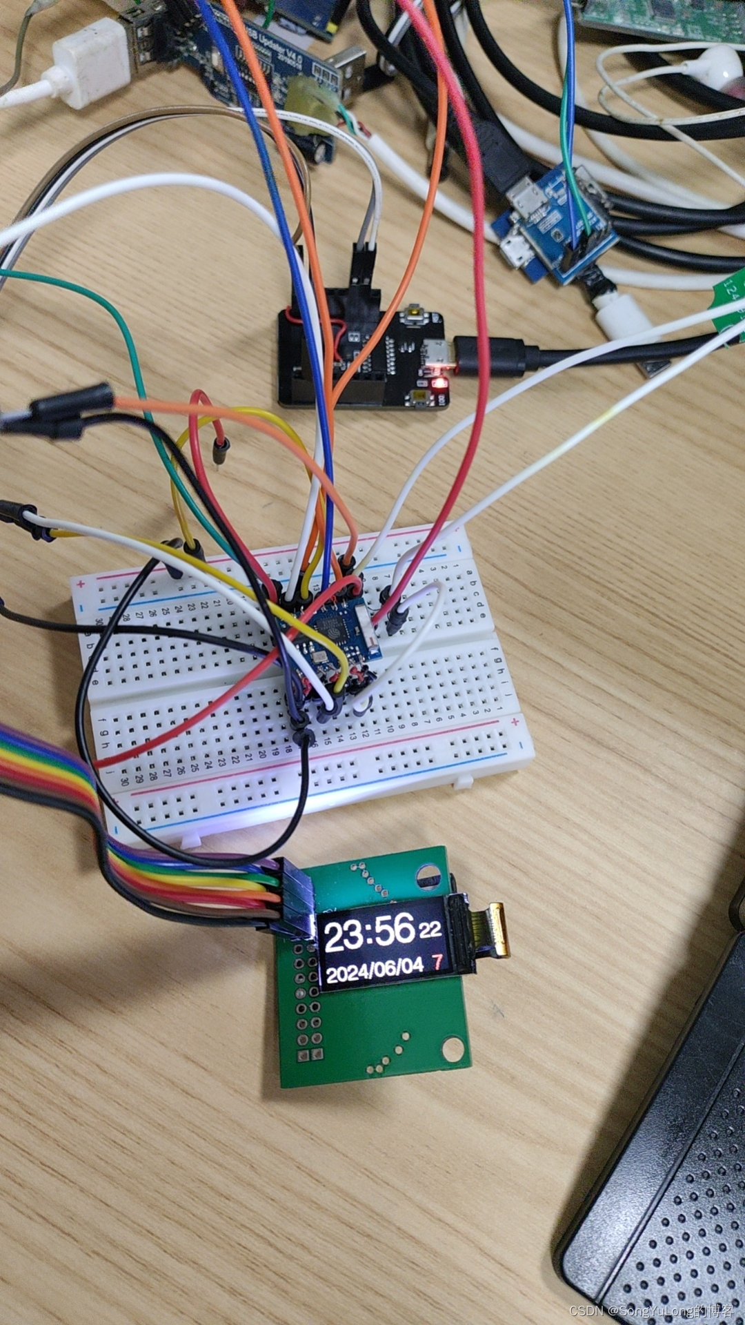
TFT_eSprite spr = TFT_eSprite(&tft);void setup() {// put your setup code here, to run once:Serial.begin(115200);Serial.println("demo...");tft.init(); // 初始化tft.setRotation(1); // 设置屏幕方向,0:0度,1:90度,2:180度,3:270度tft.fillScreen(TFT_BLACK); // 设置屏幕背景颜色tft.setTextColor(TFT_WHITE, TFT_BLACK); // 参数1:字体颜色,参数2:背景色}void loop() {// put your main code here, to run repeatedly:static int hour = 23;static int minute = 55;static int second = 56;char buffer[64];// 时分sprintf(buffer, "%d:%d", hour, minute);tft.setTextFont(6);tft.drawString(buffer, 0, 5);// 秒tft.setTextFont(4);tft.drawNumber(second, 160-32, 20);// 年月日tft.setTextFont(4);tft.drawString("2024/02/15", 0, 60);// 星期tft.setTextFont(4);tft.drawNumber(7, 160-32, 60);second += 1;second %= 60;if (0 == second) {minute += 1;minute %= 60;}delay(1000);Serial.printf("LCD Update:%d:%d:%d\n", hour, minute, second);
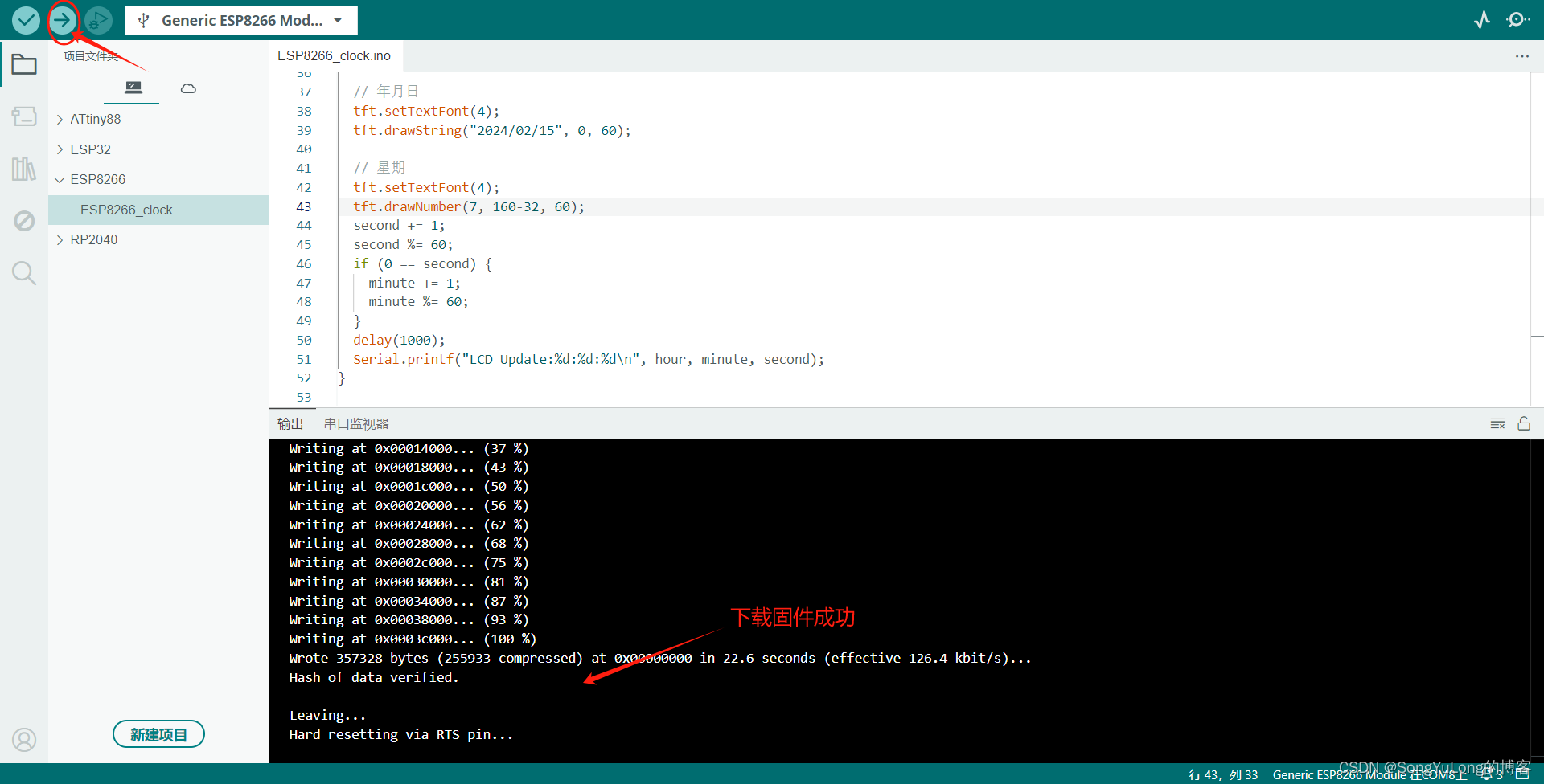
}编译下载固件
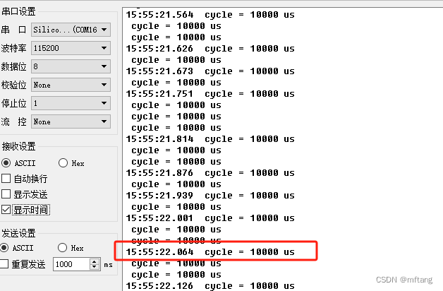
注意:先把GPIO15接GND,GPIO0接GND,CH_PD上拉(10K)再给模块供电3.3V进入UART固件下载模式。另外串口要选择实际端口:
运行效果:


![【代码随想录】【算法训练营】【第25天】 [216]组合总和III [17] 电话号码的字母组合](https://img-blog.csdnimg.cn/direct/235001571fb14d70a69e0b43098fdc76.png)