外设篇
实验箱介绍
旗舰版实验箱由2部分组成:鸿蒙外设模块(支持同时8个工作)、鸿蒙平板。
其中,鸿蒙平板默认采用RK3566方案。
OpenHarmony外设模块采用底板+传感器拓展板方式,底板默认采用ESP32方案,也可以采用STM32方案。
底板同时可以支持8个传感器外设模块、2个ESP32模块。

每个外设模块支持热插拔,采用金手指方式,方便学生根据实际学习内容更换传感器外设模块。

实验箱默认配套12~16个传感器外设模块,多的会存放到实验箱底下,学生可以自由插拔组合实验。
可以根据学校、客户需求定制传感器清单,可以支持几十种外设模块。外设篇中所用到的传感器均为实验箱配套传感器模块,读者可以自行选择购买实验箱或者购买相同模块以达到同样效果。
MQ-2烟雾传感器
模块简介
MQ-2烟雾传感器所使用的气敏材料是在清洁空气中电导率较低的二氧化锡(SnO2)。当烟雾传感器所处环境中存在可燃气体时,烟雾传感器的电导率随空气中可燃气体浓度的增加而增大。使用简单的电路即可将电导率的变化转换为与该烟雾传感器气体浓度相对应的输出信号。在使用时,会使用单片机的ADC采集对其进行信号采集该传感器可以输出模拟信号和数字信号,本文使用的是数字信号。

MQ-2气体烟雾传感器对液化气、丙烷、氢气的灵敏度高,对天然气和其它可燃蒸汽的检测也很理想。这种气体传感器可检测多种可燃性气体,是一款适合多种应用的低成本烟雾传感器。烟雾的浓度越大,导电率越大,输出电阻越低,则输出的模拟信号就越大,与MQ-7类似。
应用场景
家庭用气体泄漏报警器
工业用可燃烟雾气体报警器
便携式烟雾气体检测器
产品参数
| 型号 | MQ-2 |
| 工作电压 | DC5v |
| 工作电流 | 150mA |
| 产品类型 | 半导体器敏元器件 |
| 检测气体 | 烟雾、液化石油气、天然气和丙烷等 |
| 检测浓度 | 300~10000ppm(可燃气体) |
| 尺寸 | 32mm×20mm×22mm |
| 输出 | 支持开关数字信号、浓度模拟信号输出 |
| 重量 | 7.4g |
原理图

参考代码
BUILD.gn
# Copyright (c) 2022 Hunan OpenValley Digital Industry Development Co., Ltd.
# Licensed under the Apache License, Version 2.0 (the "License");
# you may not use this file except in compliance with the License.
# You may obtain a copy of the License at
#
#     http://www.apache.org/licenses/LICENSE-2.0
#
# Unless required by applicable law or agreed to in writing, software
# distributed under the License is distributed on an "AS IS" BASIS,
# WITHOUT WARRANTIES OR CONDITIONS OF ANY KIND, either express or implied.
# See the License for the specific language governing permissions and
# limitations under the License.import("//kernel/liteos_m/liteos.gni")
module_name = get_path_info(rebase_path("."), "name")
kernel_module(module_name){sources = ["adc_yw_example.c",]include_dirs = ["//drivers/hdf_core/framework/include/platform/","//drivers/hdf_core/framework/include/utils/","//drivers/hdf_core/framework/support/platform/include/adc","//drivers/hdf_core/adapter/khdf/liteos_m/osal/include/","//drivers/hdf_core/framework/include/core/","//drivers/hdf_core/framework/include/osal/","//drivers/hdf_core/interfaces/inner_api/utils","//device/soc/esp/esp32/components/driver/include","//device/soc/esp/esp32/components/esp_adc_cal/include","//device/soc/esp/esp32/components/driver/esp32/include",]
}
adc_yw_example.c
/** Copyright (c) 2022 Hunan OpenValley Digital Industry Development Co., Ltd.* Licensed under the Apache License, Version 2.0 (the "License");* you may not use this file except in compliance with the License.* You may obtain a copy of the License at**    http://www.apache.org/licenses/LICENSE-2.0** Unless required by applicable law or agreed to in writing, software* distributed under the License is distributed on an "AS IS" BASIS,* WITHOUT WARRANTIES OR CONDITIONS OF ANY KIND, either express or implied.* See the License for the specific language governing permissions and* limitations under the License.*/#include <stdio.h>
#include "cmsis_os2.h"
#include "ohos_run.h"
#include "osal_irq.h"/* ADC2 Example*/
#include <stdio.h>
#include <stdlib.h>
#include "driver/gpio.h"
#include "driver/adc_common.h"
#include "esp_adc_cal.h"//ADC所接的通道
#define ADC2_TEST_CHANNEL ADC2_CHANNEL_4 //ADC初始化
//ADC_ATTEN_DB_0:表示参考电压为1.1V
//ADC_ATTEN_DB_2_5:表示参考电压为1.5V
//ADC_ATTEN_DB_6:表示参考电压为2.2V
//ADC_ATTEN_DB_11:表示参考电压为3.9V
void adc_Init()
{//adc1_config_width(ADC_WIDTH_12Bit);// 12位分辨率adc2_config_channel_atten(ADC2_TEST_CHANNEL,ADC_ATTEN_DB_11);// 设置通道6和3.9V参考电压
}osThreadId_t g_taskID = NULL;static void adc_test(void)
{int read_raw;adc_Init();while(1){esp_err_t r = adc2_get_raw( ADC2_TEST_CHANNEL, ADC_WIDTH_12Bit, &read_raw);if ( r == ESP_OK ) {printf("adc value is %d\n", read_raw );} else if ( r == ESP_ERR_TIMEOUT ) {printf("ADC2 used by Wi-Fi.\n");}//ADC的结果转换成电压osDelay(1000);}
}static void adc_task(void)
{osThreadAttr_t attr;attr.name = "adc_test";attr.attr_bits = 0U;attr.cb_mem = NULL;attr.cb_size = 0U;attr.stack_mem = NULL;attr.stack_size = 1024;attr.priority = 26;g_taskID = osThreadNew((osThreadFunc_t)adc_test, NULL, &attr);if (g_taskID == NULL) {printf("Failed to create Test ADC thread!\n");}
}OHOS_APP_RUN(adc_task);
本例程展示的是如何在LiteOS操作系统中使用ADC(模数转换器)来读取模拟信号,并在一个独立的任务中持续进行ADC采样,并将结果打印出来。
注意事项:本例程使用的esp32是adc2,该组adc用作捆扎引脚(GPIO 0,2,15),因此无法与WIFI共用
编译并烧录

在源码根目录下使用hb工具对写好的代码进行编译

选择mini级系统
同理 产品选择esp公司下的esp32

选择完毕后在源码根目录下执行hb build -f 进行编译

编译完成后会有如下界面,并且编译后的代码固件位于:out\esp32\esp32

实验现象

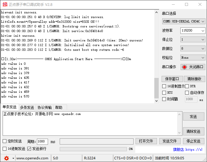
按下ESP32开发板上的EN键,即可观察到实验现象:

当传感器检测到烟雾时adc值升高到了570,实验成功!


