最近在野火的STM32F103VET6开发板上实现PMBus从机程序,这个程序参考了以下这篇博客的关于使用中断法实现I2C从机程序:STM32设置为I2C从机模式_iic从机_柒壹漆的博客-CSDN博客 ,实测这个程序是可以正常运行的,感谢博主的分享!
另外我还参考了德州仪器的一篇基于TMS320F2803x系列单片机PMBus协议的实现,包括主机和从机程序(源程序和文档下载地址:http://www.ti.com/lit/zip/SPRABJ6,文档的截图如下)。
PMBus协议的详细内容我就不说了,这里我主要说下PMBusSlave.c这个文件,代码和主要函数如下:
1、PMBusSlave_Init:初始化I2C,这里使用STM32的硬件I2C,主要配置好引脚模式为开漏输出,时钟为100K-400K之间都可以,还有从机地址和中断,另外要使能自动应答,这样从机在收到每个数据时在第9个时钟周期会把SDA拉低作为应答。
2、PMBusSlave_DecodeCommand:该函数主要是根据主机发送来的命令在数组中找到对应的命令索引从而对命令进行分组处理。如果发送的命令无效,则根据自己程序的需要进行异常处理。
3、PMBusSlave_Crc8MakeBitwise:因为绝大部分PMBus通信都使用CRC8校验,这个函数的用于检测接收到的数据是否CRC校验正确以及对发送的数据进行CRC计算。
4、I2C1_EV_IRQHandler:I2C的事件中断处理程序,这是最主要最核心的部分,绝大部分的PMBus的收发都是在此进行的。主要的几个事件分别介绍如下:
a) I2C_EVENT_SLAVE_RECEIVER_ADDRESS_MATCHED(0x00020002):
这是主机在发出START信号后,接着发送I2C从机地址(从机地址+最低位的读写位置0),如果发送的地址与当前从机的地址匹配则会产生此中断事件,此处基本不用处理,根据需要做一些变量的初始化也是可以的。
b) I2C_EVENT_SLAVE_BYTE_RECEIVED(0x00020040):
这是主机要写数据到从机时,从机接收到了数据就会产生此中断事件。在此处我们应该调用I2C_ReceiveData(I2Cx)函数保存所接收到的数据。如果主机有多个数据要发送,这个事件会多次触发。总之这个地方的主要工作就将数据保存在数据缓冲中。
c) I2C_EVENT_SLAVE_TRANSMITTER_ADDRESS_MATCHED(0x00060082):
当主机发送读操作指令时(从机地址+最低位的读写位置1),如果地址与本机地址匹配则会产生该中断事件,在该事件中我们可以开始调用函数I2C_SendData(I2Cx, data[ptr++]);发送第一个数据(可能有多个数据要发送)。此时对发送数据指针进行适当调整,以便后面的中断事件中继续发送数据。
d) I2C_EVENT_SLAVE_BYTE_TRANSMITTED(0x00060084):
当主机需要读到多个数据并且从机成功发送了一个数据后就会产生此中断事件,此处我们就根据数据指针继续调用函数2C_SendData(I2Cx, data[ptr++]发送数据,直到所有的数据都发送完成。
e) I2C_EVENT_SLAVE_STOP_DETECTED(0x00000010):
当从机检测到主机发送了STOP信号后就会产生该中断事件。此中断中一般会根据主机发送的写指令和要写入的数据进行相应的操作,例如:主机发送VOUT_COMMAND(0x21)对电源的输出电压进行设置,另外当主机读取完所有数据后也会发送STOP信号,此处我们可以对发送操作做一些清理工作,主要看自己程序的要求。
其实程序中最主要的是要知道在哪个中断事件编写相应的代码,其他像PMBus协议稍微看下资料就明白了,如果不使用STM32,换了一个别的单片机,只需要按照单片机对应的寄存器和事件处理程序写程序就可以了。之前我也写过ATmega16A和PIC16F系列的I2C从机程序,大同小异。
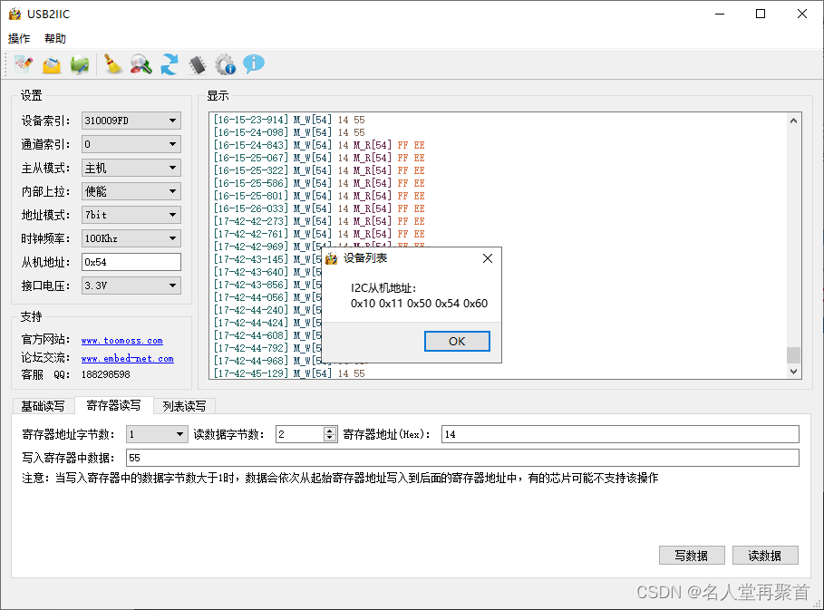
这个程序有一个问题我一直不明白,就是当主机(我使用的USB转I2C设备)进行从机扫描时会出现多个从机地址,可我明明只连接了一个I2C从机,而且执行主机扫描之后这个程序会死机,我调试发现主机发送从机扫描时,I2C_EVENT_SLAVE_RECEIVER_ADDRESS_MATCHED中断事件产生了,不明白为何这里会死机,到时我再调试下卡在哪里了。下图显示的就是主机扫描时出现的多个从机地址(我的从机地址是0x54,7位地址格式)。
main函数中只需要调用PMBusSlave_Init函数进行初始化设置就可以进入while循环,等待中断事件触发了。
好了,欢迎大家指出我的代码中存在的问题,我好改进,使程序更加健壮可靠。
/********************************************************************************* PMBusSlave.c -	This program is a software implementation of PMBus over I2C, *					with the Piccolo device acting as the PMBus slave.** Copyright (c) 2011 Texas Instruments Incorporated.  All rights reserved.* Software License Agreement* * Texas Instruments (TI) is supplying this software for use solely and* exclusively on TI's microcontroller products. The software is owned by* TI and/or its suppliers, and is protected under applicable copyright* laws. You may not combine this software with "viral" open-source* software in order to form a larger program.* * THIS SOFTWARE IS PROVIDED "AS IS" AND WITH ALL FAULTS.* NO WARRANTIES, WHETHER EXPRESS, IMPLIED OR STATUTORY, INCLUDING, BUT* NOT LIMITED TO, IMPLIED WARRANTIES OF MERCHANTABILITY AND FITNESS FOR* A PARTICULAR PURPOSE APPLY TO THIS SOFTWARE. TI SHALL NOT, UNDER ANY* CIRCUMSTANCES, BE LIABLE FOR SPECIAL, INCIDENTAL, OR CONSEQUENTIAL* DAMAGES, FOR ANY REASON WHATSOEVER.* ******************************************************************************/
//#include "DSP2803x_Device.h"     // DSP280x Headerfile Include File
//#include "DSP2803x_Examples.h"   // DSP280x Examples Include File
//#include "DSP2803x_I2C_defines.h"
#include "stm32f10x.h"
#include "stm32f10x_gpio.h"
#include "stm32f10x_i2c.h"
#include "PMBusSlave.h"
#include "PMBus.h"
#include "i2c_slave.h"#define I2C1_CLOCK_FRQ          100000     // I2C-Frq in Hz (100 kHz)struct STATUS_REGS StatusRegs;//This array contains all of the PMBus command bytes (according to the PMBus spec)
//indexed by the command indeces defined in PMBus.h
const unsigned char PMBus_Commands[120] =
{0x00, // dummy byte  0x19,0x78,0x7A,0x7B,0x7C,0x7D,0x7E,0x7F,0x80,0x81,0x82,0x98,0x79,0x88,0x89,0x8A,0x8B,0x8C,0x8D,0x8E,0x8F,0x90,0x91,0x92,0x93,0x94,0x95,0x96,0x97,0xA0,0xA1,0xA2,0xA3,0xA4,0xA5,0xA6,0xA7,0xA8,0xA9,0x13,0x14,0x17,0x18,0x3 ,0x11,0x12,0x15,0x16,0x0 ,0x1 ,0x2 ,0x4 ,0x10,0x20,0x3A,0x3D,0x41,0x45,0x47,0x49,0x4C,0x50,0x54,0x56,0x5A,0x5C,0x63,0x69,0x21,0x22,0x23,0x24,0x25,0x26,0x27,0x28,0x29,0x2A,0x31,0x32,0x33,0x35,0x36,0x37,0x38,0x39,0x3B,0x3C,0x3E,0x3F,0x40,0x42,0x43,0x44,0x46,0x48,0x4A,0x4B,0x4F,0x51,0x52,0x53,0x55,0x57,0x58,0x59,0x5B,0x5D,0x5E,0x5F,0x60,0x61,0x62,0x64,0x65,0x66,0x68,0x6A,0x6B
};static unsigned char slave_address;static uint8_t i2c1_mode = I2C1_MODE_WAITING;
//static uint8_t i2c_rcv_finish_flag = 0;//got received all data
static uint8_t i2c_rcv_cnt = 0;
static uint8_t i2c_transmit_cnt = 0;unsigned char PMBusSlave_ReceiveBuffer[4] = {0,0,0,0};
unsigned char PMBusSlave_TransmitBuffer[5] = {0xDF,0xC5,0x18,0x9F,0xB7};
unsigned char PMBusSlave_Index = 0;
unsigned char PMBusSlave_DummyCommand = 0;USER CODE
//Example variables, should be changed by user to be application specific
#warning	"User should declare application specific PMBus registers or variables."
//initial values
unsigned char Temperature = 0x88;	//0x12,STATUS_TEMPERATURE command (R byte)
unsigned char Default_Code = 0;		//STORE_DEFAULT_CODE command (W byte)
unsigned char Operation = 0x34;		//OPERATION command (R/W byte)
unsigned int Status_Word = 0x5678;	//STATUS_WORD command (R word)
unsigned char Status_Byte = 0x00;	//STATUS_BYTE command (R byte)
unsigned char Status_Cml = 0x00;	//STATUS_CML command (R byte)
unsigned int Vout_Command = 0x90AB;	//VOUT_COMMAND command (R/W word)
END USER CODE/***************************************************************************//*** @brief   Initialize I2C module in slave mode.* @param   I2CSlave_OwnAddress The slave device's own address.* @return  None******************************************************************************/
void I2CSlave_Init(uint16_t I2CSlave_OwnAddress)
{GPIO_InitTypeDef  GPIO_InitStructure;NVIC_InitTypeDef NVIC_InitStructure;I2C_InitTypeDef  I2C_InitStructure;RCC_APB1PeriphClockCmd(RCC_APB1Periph_I2C1, ENABLE);RCC_APB2PeriphClockCmd(RCC_APB2Periph_GPIOB, ENABLE);RCC_APB2PeriphClockCmd(RCC_APB2Periph_AFIO, ENABLE);/* Configure I2C_EE pins: SCL and SDA */GPIO_InitStructure.GPIO_Pin =  GPIO_Pin_6 | GPIO_Pin_7;GPIO_InitStructure.GPIO_Speed = GPIO_Speed_50MHz;GPIO_InitStructure.GPIO_Mode = GPIO_Mode_AF_OD;GPIO_Init(GPIOB, &GPIO_InitStructure);/* Configure the I2C event priority */NVIC_InitStructure.NVIC_IRQChannel                   = I2C1_EV_IRQn;NVIC_InitStructure.NVIC_IRQChannelPreemptionPriority = 0;NVIC_InitStructure.NVIC_IRQChannelSubPriority        = 0;NVIC_InitStructure.NVIC_IRQChannelCmd                = ENABLE;NVIC_Init(&NVIC_InitStructure);/* Configure I2C error interrupt to have the higher priority */NVIC_InitStructure.NVIC_IRQChannel = I2C1_ER_IRQn;NVIC_Init(&NVIC_InitStructure);/* I2C configuration */I2C_InitStructure.I2C_Mode = I2C_Mode_I2C;I2C_InitStructure.I2C_DutyCycle = I2C_DutyCycle_2;I2C_InitStructure.I2C_OwnAddress1 = I2CSLAVE_ADDR;I2C_InitStructure.I2C_Ack = I2C_Ack_Enable;I2C_InitStructure.I2C_AcknowledgedAddress = I2C_AcknowledgedAddress_7bit;I2C_InitStructure.I2C_ClockSpeed = I2C1_CLOCK_FRQ;//I2C_OwnAddress2Config(I2C1, 0x00);//configure the second I2C address/* I2C Peripheral Enable */I2C_Cmd(I2C1, ENABLE);/* Apply I2C configuration after enabling it */I2C_Init(I2C1, &I2C_InitStructure);I2C_ITConfig(I2C1, I2C_IT_EVT, ENABLE); //Part of the STM32 I2C driverI2C_ITConfig(I2C1, I2C_IT_BUF, ENABLE);I2C_ITConfig(I2C1, I2C_IT_ERR, ENABLE); //Part of the STM32 I2C driver	//======================= the original codes ============================/*//Setup Cpu Timer 0 interruptEALLOW;	// This is needed to write to EALLOW protected registersPieVectTable.TINT0 = &cpu_timer0_isr;EDIS;   // This is needed to disable write to EALLOW protected registers // Enable TINT0 in the PIE: Group 1 interrupt 7PieCtrlRegs.PIEIER1.bit.INTx7 = 1;// Enable CPU int1 which is connected to CPU-Timer 0IER |= M_INT1;InitI2CGpio();InitCpuTimers();ConfigCpuTimer(&CpuTimer0, 60, 35000);	//CPU Timer 0 interrupt after 35 ms (at 60MHz CPU freq.)// Initialize I2CI2caRegs.I2COAR = I2CSlave_OwnAddress;		// Own addressI2caRegs.I2CPSC.all = 9;		// Prescaler - need 7-12 Mhz on module clkI2caRegs.I2CCLKL = 10;			// NOTE: must be non zeroI2caRegs.I2CCLKH = 5;			// NOTE: must be non zeroI2caRegs.I2CIER.all = 0x00;		// Clear interrupts - polling based methodI2caRegs.I2CMDR.all = 0x0020;	// Take I2C out of reset// Stop I2C when suspendedreturn; */
}/***************************************************************************//*** @brief   Configure the C2000 device as a PMBus slave.* @param   PMBusSlave_DeviceAddress The slave device's own address.* @return  None******************************************************************************/
#warning "Change the GPIOs used for Alert and Control lines to match the desired GPIOs for the application."
void PMBusSlave_Init(unsigned char PMBusSlave_DeviceAddress)
{	StatusRegs.StatusWord.all = 0;			//Clear status bits for the status registers we are usingStatusRegs.StatusCml.all = 0;/*// Control Line functionality GPIO0GpioCtrlRegs.GPAPUD.bit.GPIO0 = 0;		//Enable pullup on GPIO0GpioDataRegs.GPASET.bit.GPIO0 = 1;		//Drive line highGpioCtrlRegs.GPAQSEL1.bit.GPIO0 = 0;	//SYNC to SYSCLKOUTGpioCtrlRegs.GPACTRL.bit.QUALPRD0 = 0;	//no qualification (SYNC to SYSCLKOUT)GpioCtrlRegs.GPAMUX1.bit.GPIO0 = 0;		//GPIO0 = GPIO0GpioCtrlRegs.GPADIR.bit.GPIO0 = 0;		//GPIO0 = input// SMBUS Alert functionality (GPIO2 = Alert line)GpioCtrlRegs.GPAPUD.bit.GPIO2 = 0;		//Enable pullup on GPIO2GpioDataRegs.GPASET.bit.GPIO2 = 1;		//Drive line highGpioCtrlRegs.GPAMUX1.bit.GPIO2 = 0;		//GPIO2 = GPIO2GpioCtrlRegs.GPADIR.bit.GPIO2 = 1;		//GPIO2 = output*/slave_address = PMBusSlave_DeviceAddress;I2CSlave_Init(PMBusSlave_DeviceAddress);     // Initialize USCI module
}/***************************************************************************//*** @brief   Determine what type of PMBus command was received from the master.* * 			The function also prepares data in the transmit buffer to send to * 			the master for supported READ and READ/WRITE commands. Users should modify* 			the code to implement their application's supported PMBus commands.* @param   PMBusSlave_RxCommand The command byte received from the master.* @return  Command group of the received command.******************************************************************************/
unsigned char PMBusSlave_DecodeCommand(unsigned char PMBusSlave_RxCommand)
{unsigned char PMBusSlave_CommandGroup;	for(PMBusSlave_Index = 0; PMBusSlave_Index < 120; PMBusSlave_Index++){if(PMBus_Commands[PMBusSlave_Index] == PMBusSlave_RxCommand)break;}USER CODE#warning	"User should change code to implement their application's supported PMBus commands."switch (PMBusSlave_Index)	//should include all user supported commands{case STATUS_TEMPERATURE:PMBusSlave_TransmitBuffer[0] = Temperature;break;case READ_POUT://output power for examplePMBusSlave_TransmitBuffer[0] = Vout_Command;	//lower bytePMBusSlave_TransmitBuffer[1] = Vout_Command >> 8;	//upper bytebreak;case STORE_DEFAULT_CODE:break;case OPERATION:PMBusSlave_TransmitBuffer[0] = Operation;break;case STATUS_WORD:PMBusSlave_TransmitBuffer[0] = Status_Word;	//lower bytePMBusSlave_TransmitBuffer[1] = Status_Word >> 8;	//upper bytebreak;case VOUT_COMMAND://0x21 commandPMBusSlave_TransmitBuffer[0] = Vout_Command;	//lower bytePMBusSlave_TransmitBuffer[1] = Vout_Command >> 8;	//upper bytebreak;default:PMBusSlave_DummyCommand = 1;	//command not supported by this slavebreak;}END USER CODE	if(PMBusSlave_Index == 0)//dummy byte to check if slave is presentPMBusSlave_DummyCommand = 1;if(PMBusSlave_Index > 0 && PMBusSlave_Index < 13)                  //read byte from slave devicePMBusSlave_CommandGroup = READBYTE;if(PMBusSlave_Index > 12 && PMBusSlave_Index < 40)                 // read word from slave devicePMBusSlave_CommandGroup = READWORD;if(PMBusSlave_Index > 39 && PMBusSlave_Index < 44)                 // write byte to slave devicePMBusSlave_CommandGroup = WRITEBYTE;if(PMBusSlave_Index > 43 && PMBusSlave_Index < 49)                 // send byte to slave devicePMBusSlave_CommandGroup = SENDBYTE;/* Read or write one byte of data. R/W oprn. decided based on RWFlag *******/if(PMBusSlave_Index > 48 && PMBusSlave_Index < 69) {PMBusSlave_CommandGroup = RWBYTE;}/* Read or write one word of data. R/W oprn. decided based on RWFlag *******/if(PMBusSlave_Index > 68 && PMBusSlave_Index < 120)                // R/W Word{PMBusSlave_CommandGroup = RWWORD;}	//*****************************************//illegal index - invalid command trap//===Here we don't enter dead loop===//if(PMBusSlave_Index >= 120)//while(1); //*****************************************return PMBusSlave_CommandGroup;
}static void PMBus_ClearFlag(void)
{/* ADDR Flag clear */while((I2C1->SR1 & I2C_SR1_ADDR) == I2C_SR1_ADDR) {I2C1->SR1;I2C1->SR2;}/* STOPF Flag clear */while((I2C1->SR1&I2C_SR1_STOPF) == I2C_SR1_STOPF) {I2C1->SR1;I2C1->CR1 |= 0x1;}
}void I2C1_ER_IRQHandler(void)
{if (I2C_GetITStatus(I2C1, I2C_IT_AF)) {I2C_ClearITPendingBit(I2C1, I2C_IT_AF);}
}/***************************************************************************//*** @brief   Receives a command from the master and performs reads and writes accordingly.* * 			This function should be modified by the user for their application's * 			supported commands to make function calls to carry out the commands* 			(e.g. adjusting fan speed)* @param   None* @return  None******************************************************************************/
//void PMBusSlave(void)
void I2C1_EV_IRQHandler(void)
{unsigned char PMBusSlave_Command = 0, PMBusSlave_CommandType = 0;uint8_t wert;uint32_t event;	unsigned char PMBusSlave_CrcMsgSize = 0;unsigned char PMBusSlave_CrcMsg[5];unsigned char PMBusSlave_CrcMasterGenerated = 0;unsigned char PMBusSlave_CrcSlaveGenerated = 0;PMBusSlave_CrcMsg[0] = slave_address << 1; //Reading last eventevent = I2C_GetLastEvent(I2C1);	switch(event){//Master has sent the slave address and prepared to send data to the slave//and the slave address is matched the slave device.//There is a problem that once the master sends out a broadcast address, //this system is halted on this event. case I2C_EVENT_SLAVE_RECEIVER_ADDRESS_MATCHED:			i2c1_mode = I2C1_MODE_SLAVE_ADR_WR;break;// Master has sent a byte to the slavecase I2C_EVENT_SLAVE_BYTE_RECEIVED:wert = I2C_ReceiveData(I2C1);PMBusSlave_ReceiveBuffer[i2c_rcv_cnt] = wert;i2c_rcv_cnt++;break;//Master has sent the slave address(R) and the slave prepares to send data to the mastercase I2C_EVENT_SLAVE_TRANSMITTER_ADDRESS_MATCHED:i2c1_mode = I2C1_MODE_SLAVE_ADR_RD;PMBusSlave_ReceiveBuffer[0] = I2C_ReceiveData(I2C1); PMBusSlave_Command = PMBusSlave_ReceiveBuffer[0];	//get register value received prior to this step	PMBusSlave_CommandType = PMBusSlave_DecodeCommand(PMBusSlave_Command);			switch(PMBusSlave_CommandType){//Implementation with Packet Error Checkingcase READBYTE: // master reading byte from slave//setup PEC bytei2c_transmit_cnt = 0;PMBusSlave_TransmitBuffer[0] = 0x99;//example dataPMBusSlave_CrcMsg[1] = PMBusSlave_Command;  			// store first rx bytePMBusSlave_CrcMsg[2] = (slave_address << 1) + 1;		// store slave address + R/W=1PMBusSlave_CrcMsg[3] = PMBusSlave_TransmitBuffer[0];	// store tx byte 1PMBusSlave_CrcMsgSize = 4;PMBusSlave_CrcSlaveGenerated = PMBusSlave_Crc8MakeBitwise(CRC8_INIT_REM, CRC8_POLY, PMBusSlave_CrcMsg, PMBusSlave_CrcMsgSize);PMBusSlave_TransmitBuffer[1] = PMBusSlave_CrcSlaveGenerated;I2C_SendData(I2C1, PMBusSlave_TransmitBuffer[i2c_transmit_cnt]);					i2c_transmit_cnt++;break;           case READWORD:  // master reading word from slave//setup PEC bytei2c_transmit_cnt = 0;PMBusSlave_TransmitBuffer[0] = 0xAB;	//lower bytePMBusSlave_TransmitBuffer[1] = 0x90;	//upper bytePMBusSlave_CrcMsg[1] = PMBusSlave_Command;  			// store first rx bytePMBusSlave_CrcMsg[2] = (slave_address << 1) + 1;		// store slave address + R/W=1PMBusSlave_CrcMsg[3] = PMBusSlave_TransmitBuffer[0];	// store tx byte 1PMBusSlave_CrcMsg[4] = PMBusSlave_TransmitBuffer[1];   	// store tx byte 2PMBusSlave_CrcMsgSize = 5;PMBusSlave_CrcSlaveGenerated = PMBusSlave_Crc8MakeBitwise(CRC8_INIT_REM, CRC8_POLY, PMBusSlave_CrcMsg, PMBusSlave_CrcMsgSize);PMBusSlave_TransmitBuffer[2] = PMBusSlave_CrcSlaveGenerated;I2C_SendData(I2C1, PMBusSlave_TransmitBuffer[i2c_transmit_cnt]);					i2c_transmit_cnt++;break;case RWWORD:	//read/write word//setup PEC bytei2c_transmit_cnt = 0;PMBusSlave_TransmitBuffer[0] = 0xF8;	//lower byte of example dataPMBusSlave_TransmitBuffer[1] = 0xD9;	//upper bytePMBusSlave_CrcMsg[1] = PMBusSlave_Command;  			// store first rx bytePMBusSlave_CrcMsg[2] = (slave_address << 1) + 1;		// store slave address + R/W=1PMBusSlave_CrcMsg[3] = PMBusSlave_TransmitBuffer[0];	// store tx byte 1PMBusSlave_CrcMsg[4] = PMBusSlave_TransmitBuffer[1];   	// store tx byte 2PMBusSlave_CrcMsgSize = 5;PMBusSlave_CrcSlaveGenerated = PMBusSlave_Crc8MakeBitwise(CRC8_INIT_REM, CRC8_POLY, PMBusSlave_CrcMsg, PMBusSlave_CrcMsgSize);PMBusSlave_TransmitBuffer[2] = PMBusSlave_CrcSlaveGenerated;I2C_SendData(I2C1, PMBusSlave_TransmitBuffer[i2c_transmit_cnt]);					i2c_transmit_cnt++;break;//used to send error message if the command can't be recognizeddefault://setup PEC bytei2c_transmit_cnt = 0;PMBusSlave_TransmitBuffer[0] = 0xFF;	//lower bytePMBusSlave_TransmitBuffer[1] = 0xEE;	//upper bytePMBusSlave_CrcMsg[1] = PMBusSlave_Command;  			// store first rx bytePMBusSlave_CrcMsg[2] = (slave_address << 1) + 1;		// store slave address + R/W=1PMBusSlave_CrcMsg[3] = PMBusSlave_TransmitBuffer[0];	// store tx byte 1PMBusSlave_CrcMsg[4] = PMBusSlave_TransmitBuffer[1];   	// store tx byte 2PMBusSlave_CrcMsgSize = 5;PMBusSlave_CrcSlaveGenerated = PMBusSlave_Crc8MakeBitwise(CRC8_INIT_REM, CRC8_POLY, PMBusSlave_CrcMsg, PMBusSlave_CrcMsgSize);PMBusSlave_TransmitBuffer[2] = PMBusSlave_CrcSlaveGenerated;I2C_SendData(I2C1, PMBusSlave_TransmitBuffer[i2c_transmit_cnt]);					i2c_transmit_cnt++;break;}break;//The slave device has to send the next byte to the master if neededcase I2C_EVENT_SLAVE_BYTE_TRANSMITTED://I2C_SendData(I2C1, PMBusSlave_TransmitBuffer[i2c_transmit_cnt]);//i2c_transmit_cnt++;i2c1_mode = I2C1_MODE_DATA_BYTE_RD;if(i2c_transmit_cnt < sizeof(PMBusSlave_TransmitBuffer)){I2C_SendData(I2C1, PMBusSlave_TransmitBuffer[i2c_transmit_cnt]);i2c_transmit_cnt++;}else{i2c_transmit_cnt = 0;	}			break;//The slave has received all data from the master and then prepares to write data or other operations accordingly.case I2C_EVENT_SLAVE_STOP_DETECTED:			if(i2c_rcv_cnt > 0){PMBusSlave_Command = PMBusSlave_ReceiveBuffer[0];	//get the received data		PMBusSlave_CommandType = PMBusSlave_DecodeCommand(PMBusSlave_Command);switch(PMBusSlave_CommandType){case WRITEWORD:  // master writing word to slave							PMBusSlave_CrcMasterGenerated = PMBusSlave_ReceiveBuffer[3];	//get the received PEC byte from master							//calculate PEC byte for comparisonPMBusSlave_CrcMsg[1] = PMBusSlave_Command;			// store first rx bytePMBusSlave_CrcMsg[2] = PMBusSlave_ReceiveBuffer[1];	// store rx bytePMBusSlave_CrcMsg[3] = PMBusSlave_ReceiveBuffer[2];	// store rx bytePMBusSlave_CrcMsgSize = 4;                 			// # of bytesPMBusSlave_CrcSlaveGenerated = PMBusSlave_Crc8MakeBitwise(CRC8_INIT_REM, CRC8_POLY, PMBusSlave_CrcMsg, PMBusSlave_CrcMsgSize);          			        //if the bytes do not match, respond according to the PMBus Spec.if(PMBusSlave_CrcSlaveGenerated != PMBusSlave_CrcMasterGenerated)	//compare received PEC byte with calculated PEC byte{			   			//Flush the received command byte and any received dataPMBusSlave_Command = 0;				//flush command bytePMBusSlave_Index = 0;				//clear index so no data is storedPMBusSlave_ReceiveBuffer[0] = 0;	//flush received data bytesPMBusSlave_ReceiveBuffer[1] = 0;PMBusSlave_ReceiveBuffer[2] = 0;PMBusSlave_ReceiveBuffer[3] = 0;//ERROR process if needed}break;case RWWORD:	//read/write word//while(!I2caRegs.I2CSTR.bit.AAS);	//wait until addressed by master//if (I2caRegs.I2CSTR.bit.SDIR == 0)	//determine if slave should send/receive{	//slave receiver			  				PMBusSlave_CrcMasterGenerated = PMBusSlave_ReceiveBuffer[3];//get the received PEC byte from master//calculate PEC byte for comparisonPMBusSlave_CrcMsg[1] = PMBusSlave_Command;			// store first rx bytePMBusSlave_CrcMsg[2] = PMBusSlave_ReceiveBuffer[1];	// store rx bytePMBusSlave_CrcMsg[3] = PMBusSlave_ReceiveBuffer[2];	// store rx bytePMBusSlave_CrcMsgSize = 4;                 			// # of bytesPMBusSlave_CrcSlaveGenerated = PMBusSlave_Crc8MakeBitwise(CRC8_INIT_REM, CRC8_POLY, PMBusSlave_CrcMsg, PMBusSlave_CrcMsgSize);          			        //if the bytes do not match, respond according to the PMBus Spec.if(PMBusSlave_CrcSlaveGenerated != PMBusSlave_CrcMasterGenerated)	//compare received PEC byte with calculated PEC byte{			   			//Flush the received command byte and any received dataPMBusSlave_Command = 0;				//flush command bytePMBusSlave_Index = 0;				//clear index so no data is storedPMBusSlave_ReceiveBuffer[0] = 0;	//flush received data bytesPMBusSlave_ReceiveBuffer[1] = 0;PMBusSlave_ReceiveBuffer[2] = 0;PMBusSlave_ReceiveBuffer[3] = 0;//ERROR process if needed}else//TODO according to the command{switch(PMBusSlave_Command){default:break;}}}break;case WRITEBYTE: // master writing single byte to slavePMBusSlave_CrcMasterGenerated = PMBusSlave_ReceiveBuffer[2];	//get the received PEC byte from master							//calculate PEC byte for comparisonPMBusSlave_CrcMsg[1] = PMBusSlave_Command;			// store first rx bytePMBusSlave_CrcMsg[2] = PMBusSlave_ReceiveBuffer[1];	// store rx byte						PMBusSlave_CrcMsgSize = 3;                 			// # of bytesPMBusSlave_CrcSlaveGenerated = PMBusSlave_Crc8MakeBitwise(CRC8_INIT_REM, CRC8_POLY, PMBusSlave_CrcMsg, PMBusSlave_CrcMsgSize);          			        //if the bytes do not match, respond according to the PMBus Spec.if(PMBusSlave_CrcSlaveGenerated != PMBusSlave_CrcMasterGenerated)	//compare received PEC byte with calculated PEC byte{			   			//Flush the received command byte and any received dataPMBusSlave_Command = 0;				//flush command bytePMBusSlave_Index = 0;				//clear index so no data is storedPMBusSlave_ReceiveBuffer[0] = 0;	//flush received data bytesPMBusSlave_ReceiveBuffer[1] = 0;PMBusSlave_ReceiveBuffer[2] = 0;//ERROR process if needed}break;					case SENDBYTE:  	//we already received the command.//while(!I2caRegs.I2CSTR.bit.RRDY);					//wait for the data//PMBusSlave_CrcMasterGenerated = I2caRegs.I2CDRR;	//get the received PEC byte from master//StopCpuTimer0();				//No timeout, so stop the timer//ReloadCpuTimer0();				//Reload the period value (35 ms timeout)//calculate PEC byte for comparisonPMBusSlave_CrcMsg[1] = PMBusSlave_Command;	// store first rx bytePMBusSlave_CrcMsgSize = 2;                 	// # of bytesPMBusSlave_CrcSlaveGenerated = PMBusSlave_Crc8MakeBitwise(CRC8_INIT_REM, CRC8_POLY, PMBusSlave_CrcMsg, PMBusSlave_CrcMsgSize);         //if the bytes do not match, respond according to the PMBus Spec.if(PMBusSlave_CrcSlaveGenerated != PMBusSlave_CrcMasterGenerated)	//compare received PEC byte with calculated PEC byte{			   			//Flush the received command bytePMBusSlave_Command = 0;			//flush command bytePMBusSlave_Index = 0;			//clear index so no data is stored//Set status bits//StatusRegs.StatusWord.StatusByte.bit.CML = 1;				//set the CML bit//StatusRegs.StatusCml.bit.PACKET_ERROR_CHECK_FAILED = 1;		//set the PEC failed bit//signal the master via the Alert line//GpioDataRegs.GPACLEAR.bit.GPIO2 = 1;		//Drive line low}		        break;	//User could insert handling code here.							default:break;}i2c_rcv_cnt = 0;}PMBus_ClearFlag();i2c1_mode = I2C1_MODE_WAITING;break;default:break;}//    //Event handle//    if(event == I2C_EVENT_SLAVE_RECEIVER_ADDRESS_MATCHED) //    {//        // Master has sent the slave address to send data to the slave//        i2c1_mode = I2C1_MODE_SLAVE_ADR_WR;//    }//    else if(event == I2C_EVENT_SLAVE_BYTE_RECEIVED) //    {//        // Master has sent a byte to the slave//        wert = I2C_ReceiveData(I2C1);//		PMBusSlave_ReceiveBuffer[i2c_rcv_cnt] = wert;//		i2c_rcv_cnt++;//		//		/*=========== the old statements ================//        // Check address//        if(i2c1_mode == I2C1_MODE_SLAVE_ADR_WR) //        {//            i2c1_mode = I2C1_MODE_ADR_BYTE;//            // Set current ram address//            i2c1_ram_adr = wert;//        }//        else //        {//            i2c1_mode = I2C1_MODE_DATA_BYTE_WR;//            // Store data in RAM//            Set_I2C1_Ram(i2c1_ram_adr, wert);			//            // Next ram adress//            i2c1_ram_adr++;			//        }*///    }//    else if(event == I2C_EVENT_SLAVE_TRANSMITTER_ADDRESS_MATCHED) //    {//        // Master has sent the slave address to read data from the slave//        i2c1_mode = I2C1_MODE_SLAVE_ADR_RD;//        // Read data from RAM//        wert = Get_I2C1_Ram(i2c1_ram_adr);//        // Send data to the master//        I2C_SendData(I2C1, wert);//        // Next ram adress//        i2c1_ram_adr++;//    }//    else if(event == I2C_EVENT_SLAVE_BYTE_TRANSMITTED) //    {//        // Master wants to read another byte of data from the slave//        i2c1_mode = I2C1_MODE_DATA_BYTE_RD;//        // Read data from RAM//        wert = Get_I2C1_Ram(i2c1_ram_adr);//        // Send data to the master//        I2C_SendData(I2C1, wert);//        // Next ram adress//        i2c1_ram_adr++;//    }//    else if(event == I2C_EVENT_SLAVE_STOP_DETECTED) //    {//        // Master has STOP sent//		if(i2c_rcv_cnt)//		{//			i2c_rcv_finish_flag = 1;//		}//        PMBus_ClearFlag();//        i2c1_mode = I2C1_MODE_WAITING;//    }//I2C error checkif (I2C_GetITStatus(I2C1, I2C_IT_AF)) {I2C_ClearITPendingBit(I2C1, I2C_IT_AF);//i2c_rcv_finish_flag = 0;}USER CODE//contains what actions to take after getting information from the master,//usually where to store received data and what functions to call in response#warning	"User should modify code to implement their application's supported PMBus commands."switch (PMBusSlave_Index)	//should include all user supported commands{case STATUS_TEMPERATURE:break;case STORE_DEFAULT_CODE:Default_Code = PMBusSlave_ReceiveBuffer[0];break;case OPERATION:Operation = PMBusSlave_ReceiveBuffer[0];break;case STATUS_WORD:break;case VOUT_COMMAND:Vout_Command = (PMBusSlave_ReceiveBuffer[1] << 8) | PMBusSlave_ReceiveBuffer[0];break;default:	//command not supported by this slavebreak;}END USER CODE}#if PEC
/***************************************************************************//*** @brief   Calculate the Packet Error Checking byte.* @param   PMBusSlave_CRC Initial value.* @param	PMBusSlave_Poly The polynomial to use for the calculation.* @param	*PMBusSlave_PMsg Pointer to the bytes from the PMBus transaction.* @param	PMBusSlave_MsgSize Number of bytes in the last transaction.* @return  The PEC byte.******************************************************************************/
static unsigned short PMBusSlave_Crc8MakeBitwise(unsigned char PMBusSlave_CRC, unsigned char PMBusSlave_Poly, unsigned char *PMBusSlave_Pmsg, unsigned int PMBusSlave_MsgSize)
{unsigned int i, j, carry;unsigned char msg;PMBusSlave_CRC = *PMBusSlave_Pmsg++;        	// first byte loaded in "crc"		for(i = 0 ; i < PMBusSlave_MsgSize-1 ; i ++){msg = *PMBusSlave_Pmsg++;                   // next byte loaded in "msg"for(j = 0 ; j < 8 ; j++){carry = PMBusSlave_CRC & 0x80;               			// check if MSB=1			PMBusSlave_CRC = (PMBusSlave_CRC << 1) | (msg >> 7);    // Shift 1 bit of next byte into crcif(carry) PMBusSlave_CRC ^= PMBusSlave_Poly;      		// If MSB = 1, perform XORmsg <<= 1;                  							// Shift left msg byte by 1msg &= 0x00FF;}}// The previous loop computes the CRC of the input bit stream. To this, // 8 trailing zeros are padded and the CRC of the resultant value is // computed. This gives the final CRC of the input bit stream.for(j = 0 ; j < 8 ; j++){carry = PMBusSlave_CRC & 0x80;PMBusSlave_CRC <<= 1;if(carry) PMBusSlave_CRC ^= PMBusSlave_Poly;}	PMBusSlave_CRC &= 0x00FF;	//We only want one byte (lower)return(PMBusSlave_CRC);
}
#endif/***************************************************************************//*** @brief   Handles timeouts. Triggered if clock held low > 35ms.* @param   None* @return  None******************************************************************************/
/*
interrupt void cpu_timer0_isr(void)
{// Timed out. Reset module.I2caRegs.I2CMDR.bit.IRS = 0;	//reset// Acknowledge this interrupt to receive more interrupts from group 1PieCtrlRegs.PIEACK.all = PIEACK_GROUP1;
}
*/