文章目录
- arduino - UNO-R3,mega2560-R3,NUCLEO-H723ZG的引脚定义区别
- 概述
- 笔记
- NUCLEO-H723ZG
- mega2560-R3
- UNO-R3
- 经过比对, 这2个板子(NUCLEO-H723ZG, mega2560-R3)都是和UNO-R3的arduino引脚定义一样的.
- mega2560-r3和NUCLEO-H723ZG的区别
- 补充
- arduino uno r3的纯数字IO和模拟IO作为作数字IO的测试
- arduino uno r3的串口测试
- mega2560r3的数字IO(包括模拟IO当作数字IO)的测试
- mega2560r3的串口测试
- NUCLEO-H723ZG的数字IO(包括模拟IO当作数字IO用)测试
- NUCLEO-H723ZG的串口测试
- NUCLEO-H723ZG的串口测试-物理串口
- NUCLEO-H723ZG的串口测试-单个软串口是否正常能用?
- NUCLEO-H723ZG的串口测试-单个软串口只有发送功能是否好使?
- NUCLEO-H723ZG的串口测试-单个软串口只有接收功能是否好使?
- 总结 - 只使用一根线的软串口定义
- NUCLEO-H723ZG的串口测试-定义巨量(200个)只使用1根线的软串口, 内存占用量如何?是否好使?
- 实验总结
- END
arduino - UNO-R3,mega2560-R3,NUCLEO-H723ZG的引脚定义区别
概述
飞达控制板的主控板用的mega256-r3, 由于内存不够, 想换成NUCLEO-H723ZG.
这就涉及到改底板接口, 有点不确定的地方, 先确认完, 做过实验之后, 再改板子. 要不发现不合适时, 底板就要重新做了.
NUCLEO-H723ZG说明上说, arduino引脚引出是兼容UNO-R3的.
mega2560-R3说明上并没有看到又说和UNO-R3兼容.
UNO-R3的说明稍后去找.
先确认一下3个板子的arduino引出管脚是否兼容.
如果是兼容的, 就可以用我现在做好的底板, 一并将软件编程和管脚链接的不确定的地方先实验了, 心里有个底.
这些引脚, 就只关心数字IO和串口, 就用这么多.
笔记
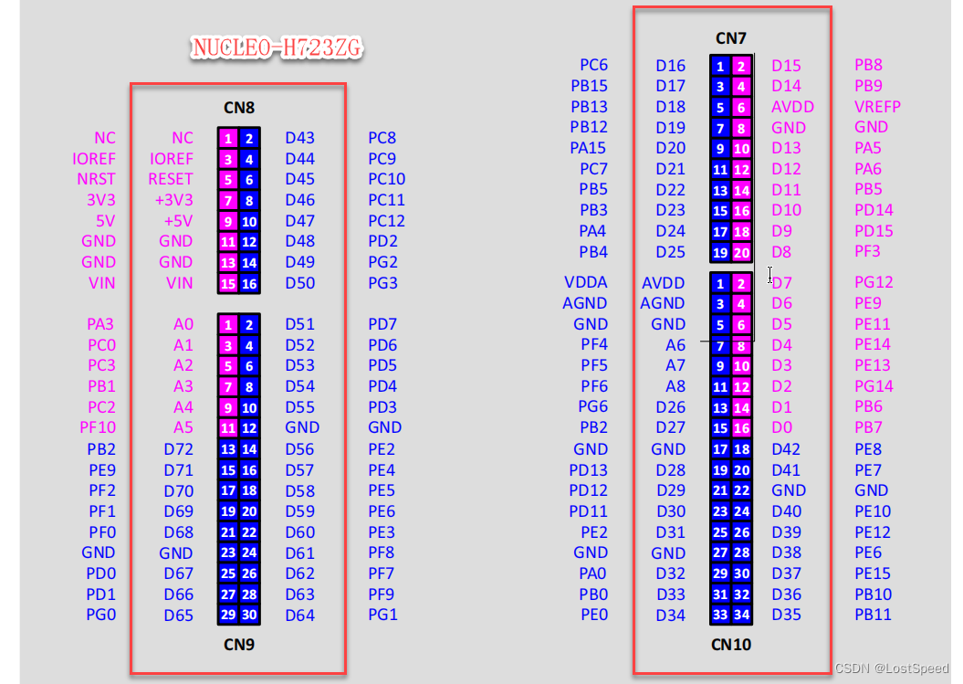
NUCLEO-H723ZG
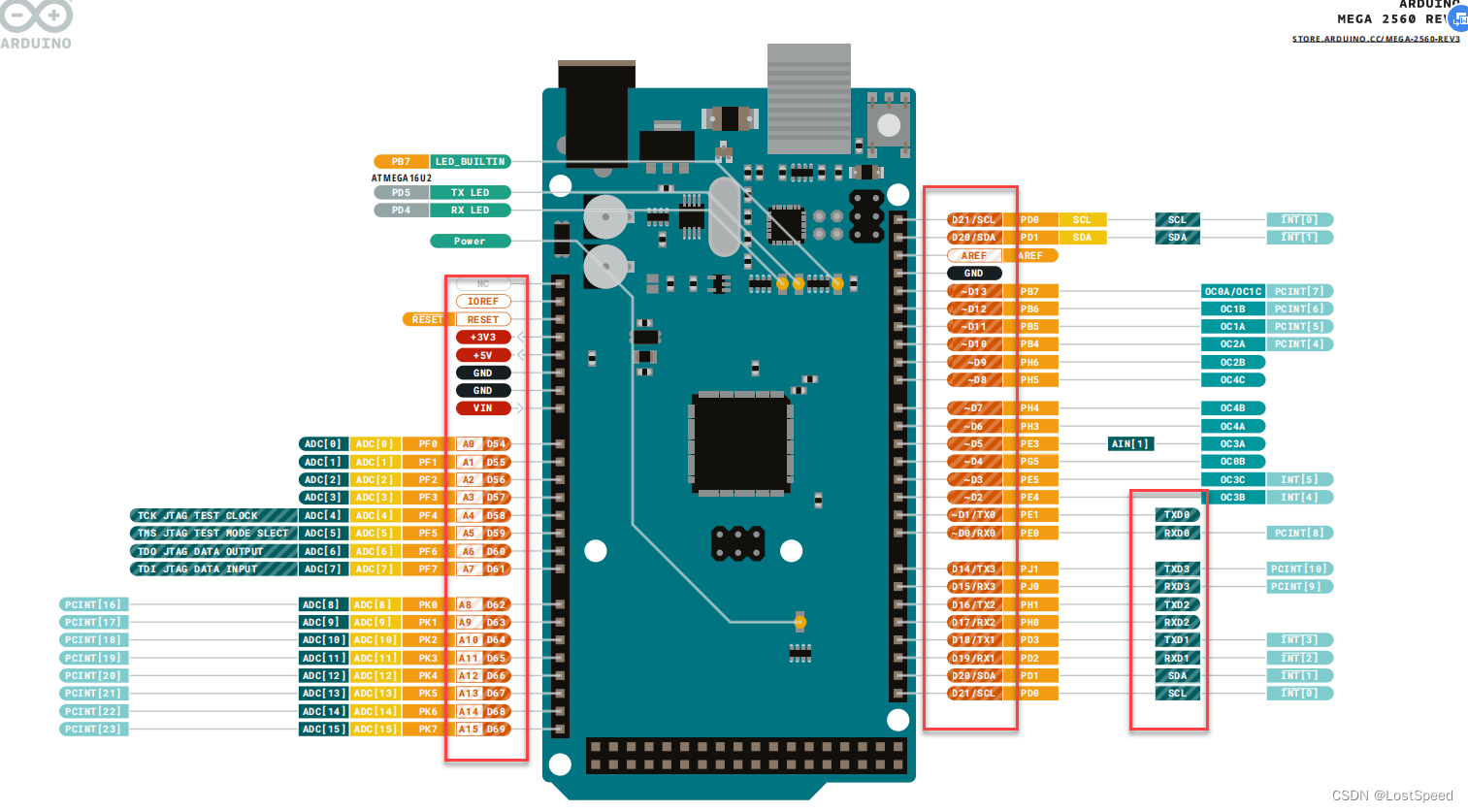
mega2560-R3
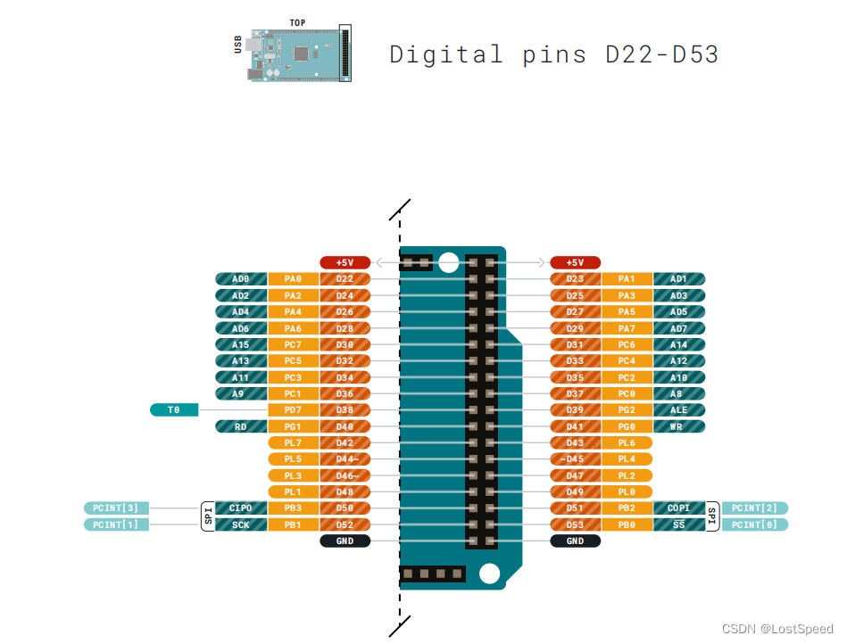
mage2560-r3下面的双排插针引脚定义
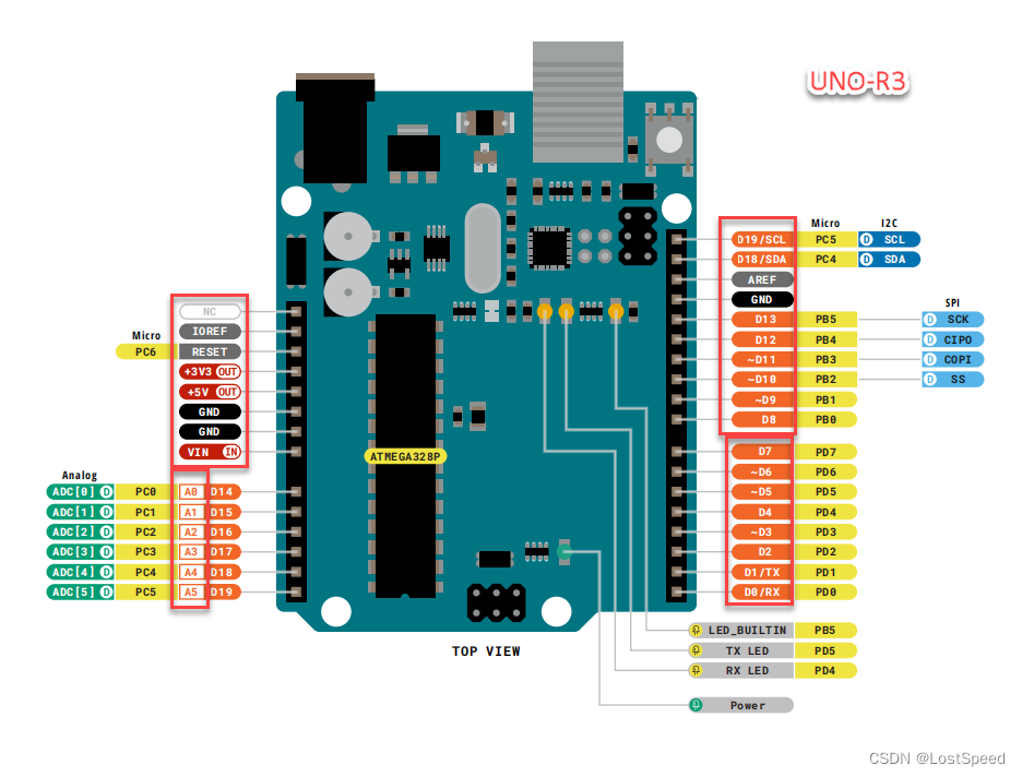
UNO-R3
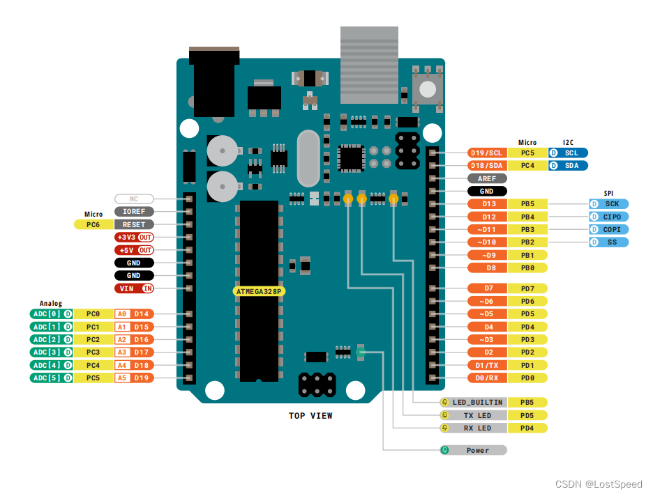
可以看到, UNO-R3的管脚引出最少.
经过比对, 这2个板子(NUCLEO-H723ZG, mega2560-R3)都是和UNO-R3的arduino引脚定义一样的.
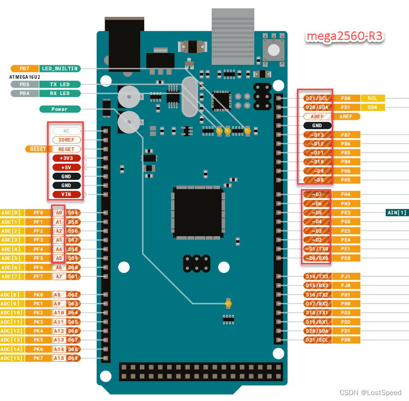
mega2560-R3右上方是D20, D21
uno-R3右上方是D18, D19
如果是当作数字IO用, 程序上要改一下.
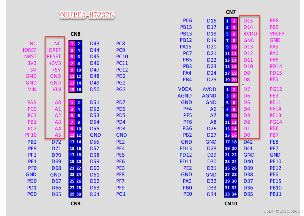
NUCLEO-H723ZG右上方是D14, D15, 也是I2C(I2C1 => PB8, PB9)
uno-R3右上方是D18, D19
如果是当作数字IO用, 程序上要改一下.
NUCLEO-H723ZG的D0, D1也是串口
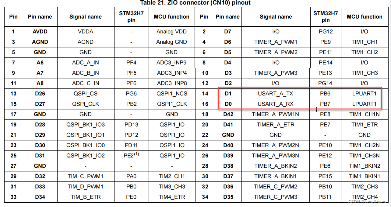
当串口用时, 程序中的串口号要改一下(串口0 to 串口1).
mega2560-r3和NUCLEO-H723ZG的区别
如果是当数字IO用, 2者也是兼容的.
看NUCLEO-H723ZG引出的串口定义是否和mega2560-r3相同?
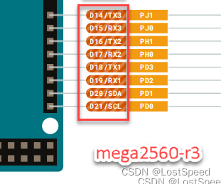
原来的底板用到了mega2560r3的D14下面的几个串口用于打印额外的调试信息(不和主串口信息干扰飞达控制), 和NUCLEO-H723ZG引出的adruino引脚定义不一样. 那看来图还得改一下(得做完软件实验再改).
补充
资料上说:
带~前缀的数字管脚是可以做PWM控制用的. e.g. ~D7
模拟IO(e.g. A0 ~ A5)也是可以当作数字IO来用的, 也是调用数字IO的函数, 参数给模拟IO的名字Ax(e.g. A1), 或者给具体的管脚号数字. 后续也一并实验了.
arduino uno r3的纯数字IO和模拟IO作为作数字IO的测试
买了官方版uno-r3, 和第三方的开发原型板.
想试试数字IO和串口收发.
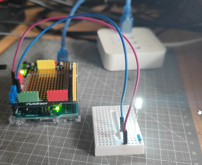
第三方开发原型板上带着LED, 不过没有串限流电阻, 点灯时, 将LED烧掉了.
用面包板和原型板连接到一起, uno IO => 680R => LED => GND
将数字IO(D0D13)和模拟IO(A0A5)当作数字IO(D14~D19)用都实验了, 将模拟IO(A0~A5)给对应的数字IO的号码就行, 使用上并没有不同.
看了几个资料, 提到模拟IO可以当作数字IO用, 没给具体例子, 自己试一下, 一下子就清楚了.
找资料时, CSDN上有些博客, 要关注博主或者要收费, 才能看这些文章, 呕吐…
这么简单的事情, 弄个开发板, 用官方例程做实验就行啊, 关注个毛线. 要收费才能看, 那就更不可能了. 都是二手资料, 弄这些骚操作有用么?
以前不怎么玩arduino, 这次要用NUCLEO-H723ZG的STM32-arduino库来弄飞达控制板(120+路的一问一答的飞达控制, 数字IO模拟串口和物理串口操作), 确实对多出来的扩展arduino管脚的用法有些不确定的地方, 得将uno-r3, mage2560r3, NUCLEO-H723ZG的全部数字IO和串口操作都在官方开发板上做完了, 心里有底了, 才能去改板子.
测试程序如下:
/*BlinkTurns an LED on for one second, then off for one second, repeatedly.Most Arduinos have an on-board LED you can control. On the UNO, MEGA and ZEROit is attached to digital pin 13, on MKR1000 on pin 6. LED_BUILTIN is set tothe correct LED pin independent of which board is used.If you want to know what pin the on-board LED is connected to on your Arduinomodel, check the Technical Specs of your board at:https://www.arduino.cc/en/Main/Productsmodified 8 May 2014by Scott Fitzgeraldmodified 2 Sep 2016by Arturo Guadalupimodified 8 Sep 2016by Colby NewmanThis example code is in the public domain.https://www.arduino.cc/en/Tutorial/BuiltInExamples/Blink
*/// env = arduino uno r3 官方版
// 验证过的管脚
// 点灯的面包板连接 IO => 680R => LED => GND
// #define MY_LED 0 // 0 is D0 => ok
// #define MY_LED 1 // 1 is D1 => ok
// #define MY_LED 2 // 2 is D2 => ok
// #define MY_LED 3 // 3 is D3 => ok
// #define MY_LED 4 // 4 is D4 => ok
// #define MY_LED 5 // 5 is D5 => ok
// #define MY_LED 6 // 6 is D6 => ok
// #define MY_LED 7 // 7 is D7 => ok
// #define MY_LED 8 // 8 is D8 => ok
// #define MY_LED 9 // 9 is D9 => ok
// #define MY_LED 10 // 10 is D10 => ok
// #define MY_LED 11 // 11 is D11 => ok
// #define MY_LED 12 // 12 is D12 => ok
// #define MY_LED 13 // 13 is D13 => ok
// #define MY_LED 18 // 18 is D18/SDA 右上角, 左下角A4/D18 => ok
// #define MY_LED 19 // 19 is D19/SSCL 右上角, 左下角A5/D19 => ok
// #define MY_LED 17 // 17 is A3/D17 => ok
// #define MY_LED 16 // 16 is A2/D16 => ok
// #define MY_LED 15 // 15 is A1/D15 => ok
#define MY_LED 14 // 14 is A0/D14 => ok// the setup function runs once when you press reset or power the board
void setup() {// initialize digital pin LED_BUILTIN as an output.pinMode(MY_LED, OUTPUT);
}// the loop function runs over and over again forever
void loop() {digitalWrite(MY_LED, HIGH);  // turn the LED on (HIGH is the voltage level)delay(1000);                      // wait for a seconddigitalWrite(MY_LED, LOW);   // turn the LED off by making the voltage LOWdelay(1000);                      // wait for a second
}
arduino uno r3的串口测试
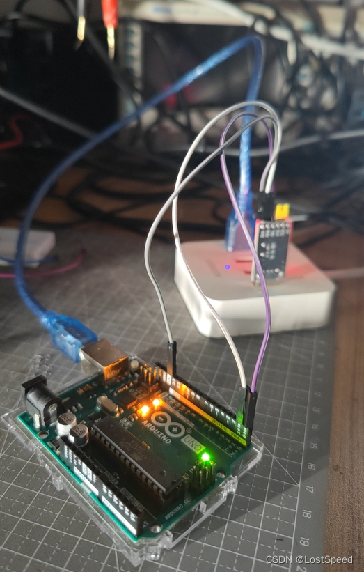
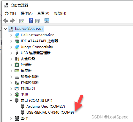
uno-r3只有1个串口, 已经预定义为Serial.
感觉用扩展板也没大用, 直接将TTL-USB串口模块接在开发板上.
测试程序
// @file uart_test.ino
// @brief 串口测试
// @note 官方串口通讯例程位置 : C:\Program Files\Arduino IDE\resources\app\lib\backend\resources\Examples\04.Communicationvoid setup() {// initialize serial:Serial.begin(9600);
}void loop() {uint8_t u8_rc = 0;delay(1000);Serial.println("hello");u8_rc = Serial.read();// 将收到的字符++, 回发// Serial.println(++u8_rc, HEX); if (0 != u8_rc){Serial.println(++u8_rc);}}
只看到板子给PC发的内容, 但是PC给板子发的内容, 接收的完全不对. 先这样, 等mega2560r3和NUCLEO-H723ZG的实验结果.
也许这个板子串口的接收引脚是坏的呢?
TTL-USB模块, 我有2个一样的. 通过2个TTL-USB互相发送, 知道TTL-USB模块是好的.
mega2560r3的数字IO(包括模拟IO当作数字IO)的测试
将工程的板子和串口改为mega2560r3的, 然后改数字IO号码, 其他并无不同.
/*BlinkTurns an LED on for one second, then off for one second, repeatedly.Most Arduinos have an on-board LED you can control. On the UNO, MEGA and ZEROit is attached to digital pin 13, on MKR1000 on pin 6. LED_BUILTIN is set tothe correct LED pin independent of which board is used.If you want to know what pin the on-board LED is connected to on your Arduinomodel, check the Technical Specs of your board at:https://www.arduino.cc/en/Main/Productsmodified 8 May 2014by Scott Fitzgeraldmodified 2 Sep 2016by Arturo Guadalupimodified 8 Sep 2016by Colby NewmanThis example code is in the public domain.https://www.arduino.cc/en/Tutorial/BuiltInExamples/Blink
*/// env = arduino uno r3 官方版
// 验证过的管脚
// 点灯的面包板连接 IO => 680R => LED => GND
// #define MY_LED 0 // 0 is D0 => ok
// #define MY_LED 1 // 1 is D1 => ok
// #define MY_LED 2 // 2 is D2 => ok
// #define MY_LED 3 // 3 is D3 => ok
// #define MY_LED 4 // 4 is D4 => ok
// #define MY_LED 5 // 5 is D5 => ok
// #define MY_LED 6 // 6 is D6 => ok
// #define MY_LED 7 // 7 is D7 => ok
// #define MY_LED 8 // 8 is D8 => ok
// #define MY_LED 9 // 9 is D9 => ok
// #define MY_LED 10 // 10 is D10 => ok
// #define MY_LED 11 // 11 is D11 => ok
// #define MY_LED 12 // 12 is D12 => ok
// #define MY_LED 13 // 13 is D13 => ok
// #define MY_LED 18 // 18 is D18/SDA 右上角, 左下角A4/D18 => ok
// #define MY_LED 19 // 19 is D19/SSCL 右上角, 左下角A5/D19 => ok
// #define MY_LED 17 // 17 is A3/D17 => ok
// #define MY_LED 16 // 16 is A2/D16 => ok
// #define MY_LED 15 // 15 is A1/D15 => ok
// #define MY_LED 14 // 14 is A0/D14 => ok// env = mega2560-r3
// 已经测试过的数字IO(包括模拟IO作为数字IO)如下
// 0 => D0
// 1 => D1
// 2 => D2
// 3 => D3
// 4 => D4
// 5 => D5
// 6 => D6
// 7 => D7
// 8 => D8
// 9 => D9
// 10 => D10
// 11 => D11
// 12 => D12
// 13 => D13
// 20 => D20
// 21 => D21// 69 => A15/D69
// 68 => A14/D68
// 67 => A13/D67
// 66 => A12/D66
// 65 => A11/D65
// 64 => A10/D64
// 63 => A9/D63
// 62 => A8/D62// 61 => A7/D61
// 60 => A6/D60
// 59 => A5/D59
// 58 => A4/D58
// 57 => A3/D57
// 56 => A2/D56
// 55 => A1/D55
// 54 => A0/D54// 14 => D14
// 15 => D15
// 16 => D16
// 17 => D17
// 18 => D18
// 19 => D19
// 20 => D20
// 21 => D21// D22 ~ D52
// 22 => D22
// 24 => D24
// 26 => D26
// 28 => D28
// 30 => D30
// 32 => D32
// 34 => D34
// 36 => D36
// 38 => D38
// 40 => D40
// 42 => D42
// 44 => D44
// 46 => D46
// 48 => D48
// 50 => D50
// 52 => D52// D23 ~ D53
// 23 => D23
// 25 => D25
// 27 => D27
// 29 => D29
// 31 => D31
// 33 => D33
// 35 => D35
// 37 => D37
// 39 => D39
// 41 => D41
// 43 => D43
// 45 => D45
// 47 => D47
// 49 => D49
// 51 => D51
// 53 => D53#define MY_LED 53// the setup function runs once when you press reset or power the board
void setup() {// initialize digital pin LED_BUILTIN as an output.pinMode(MY_LED, OUTPUT);
}// the loop function runs over and over again forever
void loop() {digitalWrite(MY_LED, HIGH); // turn the LED on (HIGH is the voltage level)delay(1000); // wait for a seconddigitalWrite(MY_LED, LOW); // turn the LED off by making the voltage LOWdelay(1000); // wait for a second
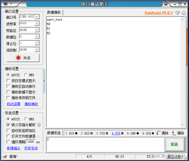
}mega2560r3的串口测试
串口0,1,2,3可用.
串口0只能从板子发信息给上位机, 和uno-r3情况相同.
串口1,2,3可以双向正常收发.
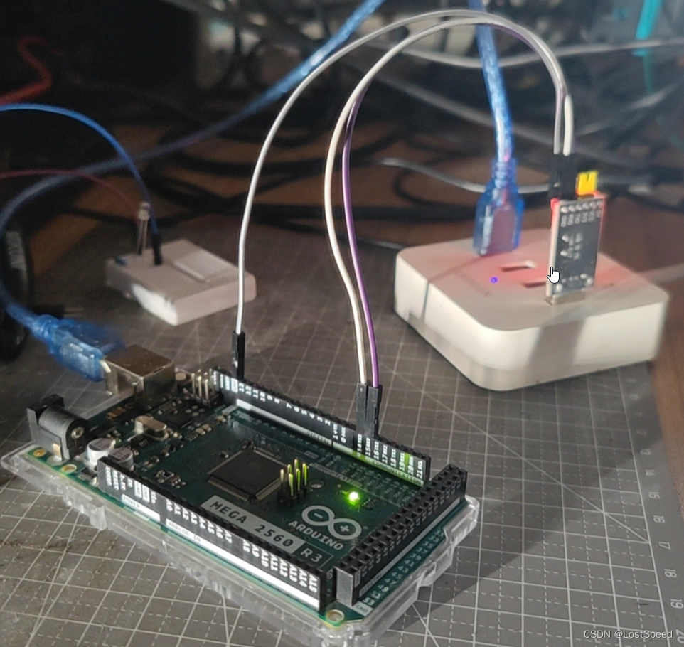
测试工程如下:
// @file uart_test.ino
// @brief 串口测试
// @note 官方串口通讯例程位置 : C:\Program Files\Arduino IDE\resources\app\lib\backend\resources\Examples\04.Communication// mega2560的串口有串口0, 1,2,3可用.
// #define MY_COM_PORT Serial // D1/TX0, D0/RX0 // 串口0不是Serial0, 而是Serial, 只能收到来自板子的消息, 发给板子的消息没响应, 跟uno-r3情况相同
// 板子程序编译上传时, 上位机串口助手收到好多乱码, 然后才是程序开始运行的提升信息, 怀疑是程序编译上传用的也是串口0, 那只用串口0作为向上位机发送信息的串口.// #define MY_COM_PORT Serial1 // D18/TX1, D19/RX1 // 测试通过, 收发正常
// #define MY_COM_PORT Serial2 // D16/TX2, D17/RX2 // 测试通过, 收发正常
#define MY_COM_PORT Serial3 // D14/TX3, D15/RX3 // 测试通过, 收发正常void setup() {// initialize serial:MY_COM_PORT.begin(9600);delay(1000);MY_COM_PORT.println("uart_test");
}void loop() {byte u8_rc = 0;// 是否收到了PC端发来的字符?if (true == MY_COM_PORT.available()){u8_rc = MY_COM_PORT.read();// 将收到的字符++, 回发MY_COM_PORT.println(++u8_rc);}
}
NUCLEO-H723ZG的数字IO(包括模拟IO当作数字IO用)测试
还好测试了, 确实发现几个不能用的数字IO.
原因是官方文档上说, 必须要动板子上的一些电阻和跳线, 如果拿官方原装的板子, 啥也不动, 就是有几个数字IO不好使(控制后没反应).
不好使的管脚一共有3个
// CN7.5 D18 I2S_A_CK PB13(2) I2S_2
// 18 => D18 // 不好使, 这个引脚不能作为数字IO// CN9.15 D71 COMP2_INP PE9 COMP2_INP
// 71 => D71 // 不好使// CN9.13 D72 COMP1_INP PB2 COMP1_INP
// 72 => D72 // 不好使
通过看STM32-Arduino的头文件, 发现NUCLEO-H723ZG模拟IO当作数字IO用时, 数字基址是0xC0. (e.g. A0是 0xC0, A5是 0xC0 + 5).
测试程序如下:
/*BlinkTurns an LED on for one second, then off for one second, repeatedly.Most Arduinos have an on-board LED you can control. On the UNO, MEGA and ZEROit is attached to digital pin 13, on MKR1000 on pin 6. LED_BUILTIN is set tothe correct LED pin independent of which board is used.If you want to know what pin the on-board LED is connected to on your Arduinomodel, check the Technical Specs of your board at:https://www.arduino.cc/en/Main/Productsmodified 8 May 2014by Scott Fitzgeraldmodified 2 Sep 2016by Arturo Guadalupimodified 8 Sep 2016by Colby NewmanThis example code is in the public domain.https://www.arduino.cc/en/Tutorial/BuiltInExamples/Blink
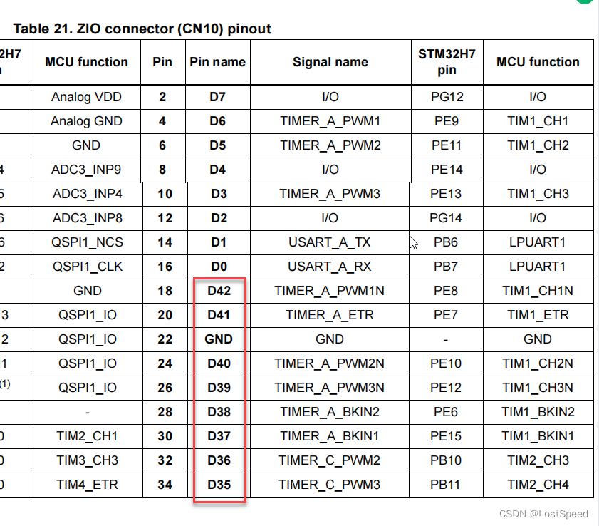
*/// env = NUCLEO-H723ZG// CN10双排插座
// 7 => D7
// 6 => D6
// 5 => D5
// 4 => D4
// 3 => D3
// 2 => D2
// 1 => D1
// 0 => D0
// 42 => D42
// 41 => D41
// 40 => D40
// 39 => D39
// 38 => D38
// 37 => D37
// 36 => D36
// 35 => D35
// 34 => D34
// 33 => D33
// 32 => D32
// 31 => D31
// 30 => D30
// 29 => D29
// 28 => D28
// 27 => D27
// 26 => D26// C:\Users\chenx\AppData\Local\Arduino15\packages\STMicroelectronics\hardware\stm32\2.6.0\cores\arduino\pins_arduino_analog.h
// #define PNUM_ANALOG_BASE 0xC0
/*
#if NUM_ANALOG_INPUTS > 0
#define PIN_A0 PNUM_ANALOG_BASE
#if NUM_ANALOG_INPUTS > 1#define PIN_A1 (PIN_A0 + 1)
#endif
#if NUM_ANALOG_INPUTS > 2#define PIN_A2 (PIN_A1 + 1)
#endif
#if NUM_ANALOG_INPUTS > 3#define PIN_A3 (PIN_A2 + 1)
#endif
#if NUM_ANALOG_INPUTS > 4#define PIN_A4 (PIN_A3 + 1)
#endif
#if NUM_ANALOG_INPUTS > 5#define PIN_A5 (PIN_A4 + 1)
#endif
#if NUM_ANALOG_INPUTS > 6#define PIN_A6 (PIN_A5 + 1)
#endif
#if NUM_ANALOG_INPUTS > 7#define PIN_A7 (PIN_A6 + 1)
#endif
#if NUM_ANALOG_INPUTS > 8#define PIN_A8 (PIN_A7 + 1)
#endif
#if NUM_ANALOG_INPUTS > 9#define PIN_A9 (PIN_A8 + 1)
#endif
*/// (0xC0 + 8) => A8
// (0xC0 + 7) => A7
// (0xC0 + 6) => A6// CN7双排插座
// 25 => D25
// 24 => D24
// 23 => D23
// 22 => D22
// 21 => D21
// 20 => D20
// 19 => D19// 官方文档说, 如果要让NUCLEO-H723ZG作为arduino使用, 必须断开一些电阻和跳线
// 因为我以前动官方板子的跳线, 将官方板子的MCU弄烧了(一块EVAL板子小几千呢, 肉疼+心疼), 所以不大敢动官方板子.
// 就拿到手之后的板子做实验, 不到刚需的程度不动官方板子.
// 因为不动那些跳线, 就会使一些功能不好使, 先这样.
// 能用的数字IO和串口就用, 不能用的就不画在板子上. 应该数字IO和串口都是有富余的, 这次主要是用NUCLEO-H723ZG的大内存.// CN7.5 D18 I2S_A_CK PB13(2) I2S_2
// 18 => D18 // 不好使, 这个引脚不能作为数字IO
// 17 => D17
// 16 => D16
// 15 => D15
// 14 => D14
// 8 => D8
// 9 => D9
// 10 => D10
// 11 => D11
// 12 => D12
// 13 => D13
// 14 => D14
// 15 => D15// CN8双排插座
// 43 => D43
// 44 => D44
// 45 => D45
// 46 => D46
// 47 => D47
// 48 => D48
// 49 => D49
// 50 => D50// CN9双排插座
// 51 => D51
// 52 => D52
// 53 => D53
// 54 => D54
// 55 => D55
// 56 => D56
// 57 => D57
// 58 => D58
// 59 => D59
// 60 => D60
// 61 => D61
// 62 => D62
// 63 => D63
// 64 => D64
// 65 => D65
// 66 => D66
// 67 => D67
// 68 => D68
// 69 => D69
// 70 => D70// CN9.15 D71 COMP2_INP PE9 COMP2_INP
// 71 => D71 // 不好使// CN9.13 D72 COMP1_INP PB2 COMP1_INP
// 72 => D72 // 不好使// (0xC0 + 5) => A5
// (0xC0 + 4) => A4
// (0xC0 + 3) => A3
// (0xC0 + 2) => A2
// (0xC0 + 1) => A1
// (0xC0 + 0) => A0#define MY_LED (0xC0 + 0)// the setup function runs once when you press reset or power the board
void setup() {// initialize digital pin LED_BUILTIN as an output.pinMode(MY_LED, OUTPUT);
}// the loop function runs over and over again forever
void loop() {digitalWrite(MY_LED, HIGH); // turn the LED on (HIGH is the voltage level)delay(500); // wait for a seconddigitalWrite(MY_LED, LOW); // turn the LED off by making the voltage LOWdelay(500); // wait for a second
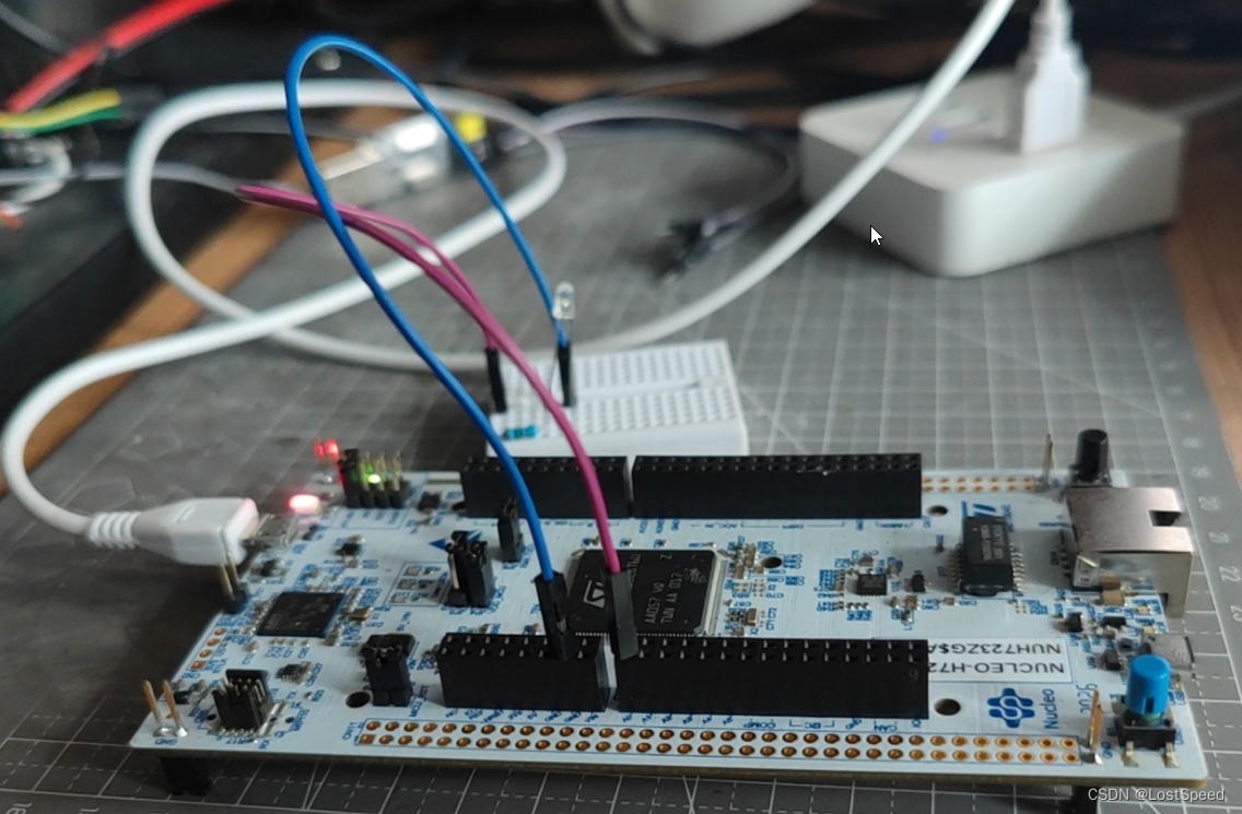
}NUCLEO-H723ZG的串口测试
板子在4个arduino兼容的插座上, 并没有引出物理串口.
唯一的物理串口是板子对上位机的串口(就是上传程序到板子的那个串口).
如果想在引出的4个arduino插座上使用串口, 就只能使用软串口(用数字IO模拟的串口)
NUCLEO-H723ZG的串口测试-物理串口
/*Software serial multiple serial testReceives from the hardware serial, sends to software serial.Receives from software serial, sends to hardware serial.The circuit:* RX is digital pin 10 (connect to TX of other device)* TX is digital pin 11 (connect to RX of other device)created back in the mists of timemodified 25 May 2012by Tom Igoebased on Mikal Hart's exampleThis example code is in the public domain.*/// 官方例程
// C:\Users\chenx\AppData\Local\Arduino15\packages\STMicroelectronics\hardware\stm32\2.6.0\libraries#include <SoftwareSerial.h>// 可用的物理串口列表
// #define MY_PH_COM_PORT Serial3 // 这个串口是对PC的那个
// Serial3 已经定义了别名 Serial
#define MY_PH_COM_PORT Serial3SoftwareSerial mySerial(10, 11); // RX, TXvoid setup() {// Open serial communications and wait for port to open:MY_PH_COM_PORT.begin(9600);while (!MY_PH_COM_PORT) {; // wait for serial port to connect. Needed for native USB port only}MY_PH_COM_PORT.println("Goodnight moon!");// set the data rate for the SoftwareSerial port// mySerial.begin(4800);// mySerial.println("Hello, world?");
}void loop() { // run over and over
/*if (mySerial.available()) {Serial.write(mySerial.read());}*/if (MY_PH_COM_PORT.available()) {// mySerial.write(MY_PH_COM_PORT.read());MY_PH_COM_PORT.write(MY_PH_COM_PORT.read() + 1);}
}
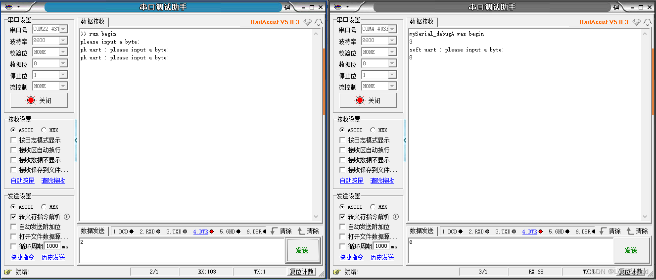
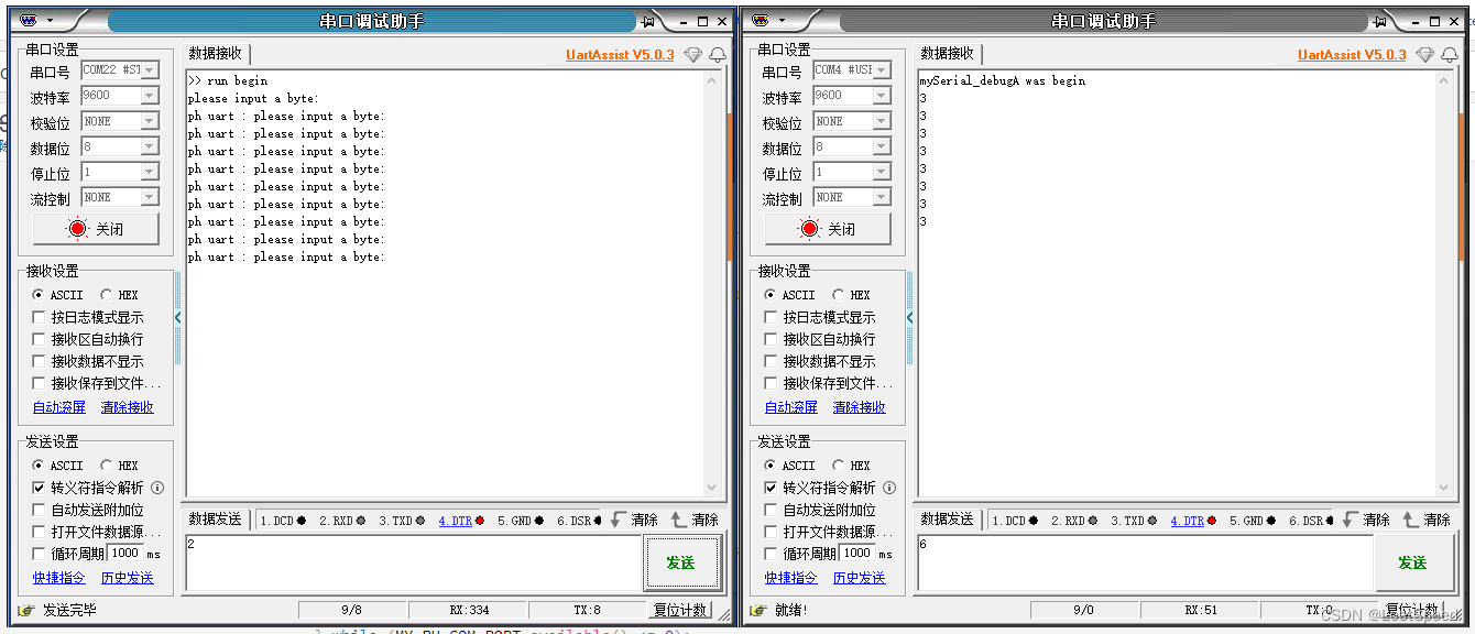
NUCLEO-H723ZG的串口测试-单个软串口是否正常能用?
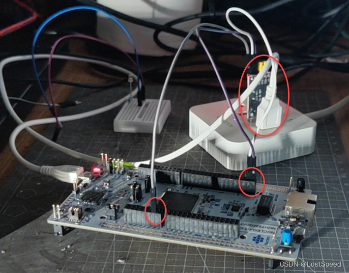
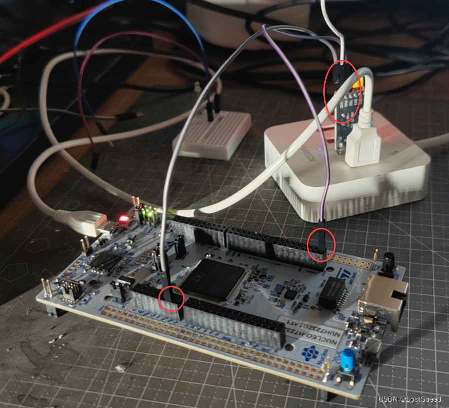
硬件连接时, 只要挑2个可用的数字IO就行, 外加一个GND, 通过TTL-USB串口模块连接到上位机.
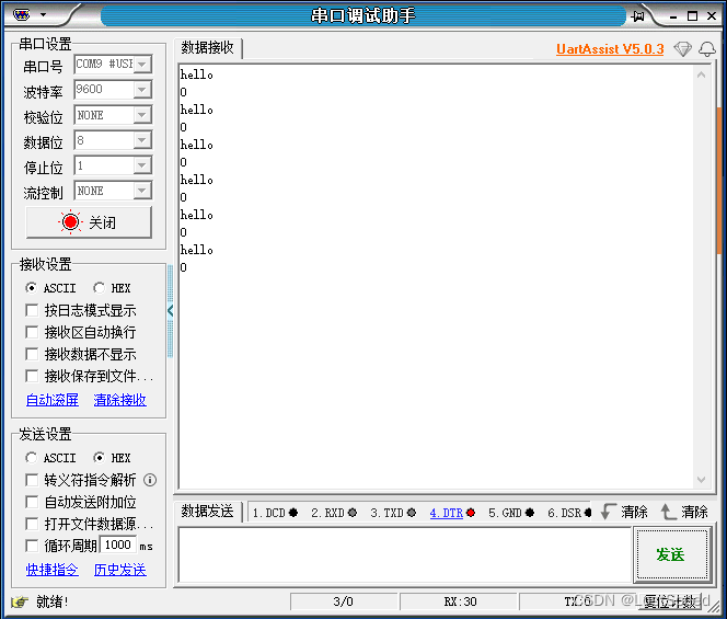
测试过了, 单个软串口好使, 板子和上位机能通讯
用板子唯一的物理串口, 一个软串口和上位机交互, 一问一答
用 串口.available() 在一个循环中, 来死等这个串口的字符接收.
测试程序如下:
/*Software serial multiple serial testReceives from the hardware serial, sends to software serial.Receives from software serial, sends to hardware serial.The circuit:* RX is digital pin 10 (connect to TX of other device)* TX is digital pin 11 (connect to RX of other device)created back in the mists of timemodified 25 May 2012by Tom Igoebased on Mikal Hart's exampleThis example code is in the public domain.*/// 官方例程
// C:\Users\chenx\AppData\Local\Arduino15\packages\STMicroelectronics\hardware\stm32\2.6.0\libraries#include <SoftwareSerial.h>// 可用的物理串口列表
// #define MY_PH_COM_PORT Serial3 // 这个串口是对PC的那个
// Serial3 已经定义了别名 Serial
#define MY_PH_COM_PORT SerialSoftwareSerial mySerial_debugA(35, 36); // RX, TXvoid setup() {// Open serial communications and wait for port to open:MY_PH_COM_PORT.begin(9600);// 等待物理串口可用while (!MY_PH_COM_PORT) {; // wait for serial port to connect. Needed for native USB port only}MY_PH_COM_PORT.println(">> run begin");MY_PH_COM_PORT.println("please input a byte: ");// set the data rate for the SoftwareSerial portmySerial_debugA.begin(9600);mySerial_debugA.println("mySerial_debugA was begin");
}void loop() { // run over and overbyte cb = 0;mySerial_debugA.listen();// 从物理串口发一个字节到板子MY_PH_COM_PORT.println("ph uart : please input a byte: ");// 等待物理串口发来东西do {} while (MY_PH_COM_PORT.available() <= 0);cb = MY_PH_COM_PORT.read();// 从软件串口将从物理串口收到的1个字节, ++, 然后从软件串口发出去mySerial_debugA.write(cb + 1);mySerial_debugA.write("\r\n");// 等待软串口发来东西mySerial_debugA.println("soft uart : please input a byte: ");do {} while (mySerial_debugA.available() <= 0);// 从软件串口收一个字节, +=2 后, 回发到软件串口cb = mySerial_debugA.read();mySerial_debugA.write(cb + 2);mySerial_debugA.write("\r\n");
}
运行效果
NUCLEO-H723ZG的串口测试-单个软串口只有发送功能是否好使?
定义一个串口只有1根线, 只管发送.
试过了好使.
这个场景, 是在控制飞达时, 只用1根线来模拟串口的发送, 只管给飞达发命令.
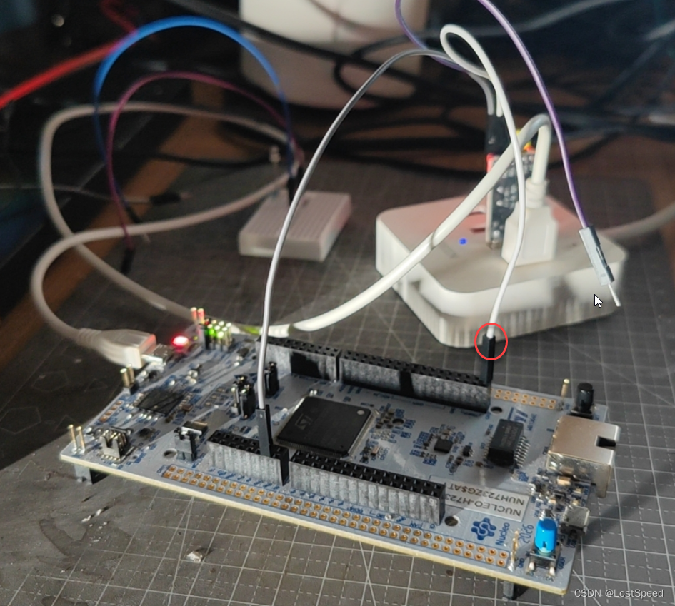
D35上这个是发送线, 对应的是TTL-USB串口模块的RX端子.
将物理串口发送的字符, 转发单根线的软串口上.
测试程序如下:
/*Software serial multiple serial testReceives from the hardware serial, sends to software serial.Receives from software serial, sends to hardware serial.The circuit:* RX is digital pin 10 (connect to TX of other device)* TX is digital pin 11 (connect to RX of other device)created back in the mists of timemodified 25 May 2012by Tom Igoebased on Mikal Hart's exampleThis example code is in the public domain.*/// 官方例程
// C:\Users\chenx\AppData\Local\Arduino15\packages\STMicroelectronics\hardware\stm32\2.6.0\libraries#include <SoftwareSerial.h>// 可用的物理串口列表
// #define MY_PH_COM_PORT Serial3 // 这个串口是对PC的那个
// Serial3 已经定义了别名 Serial
#define MY_PH_COM_PORT Serial// 飞达控制板上, 用单条的IO模拟串口发送线.
// 接收的线从飞达上汇总到一根线上, 作为几个接收.
// 现在试试定义一个软串口, 就一根线, 只用发送功能, 看行不行?
SoftwareSerial mySerial_debugA(35, 35); // RX, TX // 定义一个软串口, 只用发送功能.void setup() {// Open serial communications and wait for port to open:MY_PH_COM_PORT.begin(9600);// 等待物理串口可用while (!MY_PH_COM_PORT) {; // wait for serial port to connect. Needed for native USB port only}MY_PH_COM_PORT.println(">> run begin");MY_PH_COM_PORT.println("please input a byte: ");// set the data rate for the SoftwareSerial portmySerial_debugA.begin(9600);mySerial_debugA.println("mySerial_debugA was begin");
}void loop() { // run over and overbyte cb = 0;// 将物理串口发来的东西, 转发到软串口到上位机// 从物理串口发一个字节到板子MY_PH_COM_PORT.println("ph uart : please input a byte: ");// 等待物理串口发来东西do {} while (MY_PH_COM_PORT.available() <= 0);cb = MY_PH_COM_PORT.read();// 从软件串口将从物理串口收到的1个字节, ++, 然后从软件串口发出去mySerial_debugA.write(cb + 1);mySerial_debugA.write("\r\n");
}
测试效果
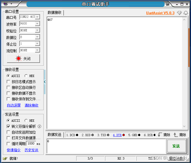
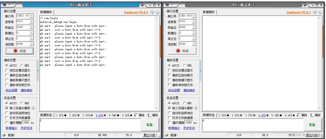
NUCLEO-H723ZG的串口测试-单个软串口只有接收功能是否好使?
硬件连接时, D35定义为串口, 只用接受功能, 将TTL-USB串口模块的发送端子接到D35.
根据物理串口的提示, 从上位机想软串口发送一个字节, 再将接收到的内容显示在上位机物理串口的串口助手中.
试过了好使.
测试程序如下:
/*Software serial multiple serial testReceives from the hardware serial, sends to software serial.Receives from software serial, sends to hardware serial.The circuit:* RX is digital pin 10 (connect to TX of other device)* TX is digital pin 11 (connect to RX of other device)created back in the mists of timemodified 25 May 2012by Tom Igoebased on Mikal Hart's exampleThis example code is in the public domain.*/// 官方例程
// C:\Users\chenx\AppData\Local\Arduino15\packages\STMicroelectronics\hardware\stm32\2.6.0\libraries#include <SoftwareSerial.h>// 可用的物理串口列表
// #define MY_PH_COM_PORT Serial3 // 这个串口是对PC的那个
// Serial3 已经定义了别名 Serial
#define MY_PH_COM_PORT Serial// 飞达控制板上, 用单条的IO模拟串口发送线.
// 接收的线从飞达上汇总到一根线上, 作为几个接收.
// 现在试试定义一个软串口, 就一根线, 只用发送功能, 看行不行?
SoftwareSerial mySerial_debugA(35, 35); // RX, TX // 定义一个软串口, 只用接收功能.void setup() {// Open serial communications and wait for port to open:MY_PH_COM_PORT.begin(9600);// 等待物理串口可用while (!MY_PH_COM_PORT) {; // wait for serial port to connect. Needed for native USB port only}MY_PH_COM_PORT.println(">> run begin");// set the data rate for the SoftwareSerial portmySerial_debugA.begin(9600);MY_PH_COM_PORT.println("mySerial_debugA was begin");
}void loop() { // run over and overbyte cb = 0;// 将物理串口发来的东西, 转发到软串口到上位机mySerial_debugA.listen(); // 软件口开始监听// 从物理串口发一个字节到板子MY_PH_COM_PORT.println("ph uart : please input a byte from soft uart : ");// 等待软串口发来东西do {} while (mySerial_debugA.available() <= 0);cb = mySerial_debugA.read();// 从软件串口将从物理串口收到的1个字节, ++, 然后从软件串口发出去MY_PH_COM_PORT.write("ph uart : recv a byte from soft uart <= ");MY_PH_COM_PORT.write(cb);MY_PH_COM_PORT.write("\r\n");
}
测试效果
总结 - 只使用一根线的软串口定义
// 参数1是接收, 参数2是发送
// 如果只想用一根线的软串口, 将发送和接收都定义成一样的数字IO的号码就行
// 当使用时, 就只使用软串口的发送(.write())或者只使用软串口的接收(.read(), 如果要死等软串口的接收字符, 就do{} while(串口.available() <= 0);)
SoftwareSerial mySerial_debugA(35, 35); // RX, TX // 定义一个软串口, 只用接收功能.
NUCLEO-H723ZG的串口测试-定义巨量(200个)只使用1根线的软串口, 内存占用量如何?是否好使?
在工程中定义了200个软串口(一个串口只使用1根线), 一个串口大约占用100~100个字节.
简单测试了其中一个软串口, 好使.
因为实际用时, 也就是使用60~70个软串口, 已经够用了. 剩余内存还是大大的有. 心里有底了.
测试工程如下:
/*Software serial multiple serial testReceives from the hardware serial, sends to software serial.Receives from software serial, sends to hardware serial.The circuit:* RX is digital pin 10 (connect to TX of other device)* TX is digital pin 11 (connect to RX of other device)created back in the mists of timemodified 25 May 2012by Tom Igoebased on Mikal Hart's exampleThis example code is in the public domain.*/// 官方例程
// C:\Users\chenx\AppData\Local\Arduino15\packages\STMicroelectronics\hardware\stm32\2.6.0\libraries#include <SoftwareSerial.h>// 可用的物理串口列表
// #define MY_PH_COM_PORT Serial3 // 这个串口是对PC的那个
// Serial3 已经定义了别名 Serial
#define MY_PH_COM_PORT Serial// 飞达控制板上, 用单条的IO模拟串口发送线.
// 接收的线从飞达上汇总到一根线上, 作为几个接收.
// 现在试试定义一个软串口, 就一根线, 只用发送功能, 看行不行?
SoftwareSerial mySerial_debugA(35, 35); // RX, TX // 定义一个软串口, 只用接收功能./*
项目使用 61756 字节(5%)的程序存储空间。最大值为 1048576 字节。个全局变量使用 1884 个字节(0%)的动态内存,剩下 325796 个字节用于局部变量。最大值为 327680 字节。
*/// 定义多个软串口时, 内存占用量如何?/*
项目使用 61780 字节(5%)的程序存储空间。最大值为 1048576 字节。个全局变量使用 1996 个字节(0%)的动态内存,剩下 325684 个字节用于局部变量。最大值为 327680 字节。// 325796 - 325684 = 112
*/SoftwareSerial mySoftUart001(35, 35); // RX, TX
SoftwareSerial mySoftUart002(35, 35); // RX, TX
SoftwareSerial mySoftUart003(35, 35); // RX, TX
SoftwareSerial mySoftUart004(35, 35); // RX, TX
SoftwareSerial mySoftUart005(35, 35); // RX, TX
SoftwareSerial mySoftUart006(35, 35); // RX, TX
SoftwareSerial mySoftUart007(35, 35); // RX, TX
SoftwareSerial mySoftUart008(35, 35); // RX, TX
SoftwareSerial mySoftUart009(35, 35); // RX, TX
SoftwareSerial mySoftUart010(35, 35); // RX, TXSoftwareSerial mySoftUart011(35, 35); // RX, TX
SoftwareSerial mySoftUart012(35, 35); // RX, TX
SoftwareSerial mySoftUart013(35, 35); // RX, TX
SoftwareSerial mySoftUart014(35, 35); // RX, TX
SoftwareSerial mySoftUart015(35, 35); // RX, TX
SoftwareSerial mySoftUart016(35, 35); // RX, TX
SoftwareSerial mySoftUart017(35, 35); // RX, TX
SoftwareSerial mySoftUart018(35, 35); // RX, TX
SoftwareSerial mySoftUart019(35, 35); // RX, TX
SoftwareSerial mySoftUart020(35, 35); // RX, TXSoftwareSerial mySoftUart021(35, 35); // RX, TX
SoftwareSerial mySoftUart022(35, 35); // RX, TX
SoftwareSerial mySoftUart023(35, 35); // RX, TX
SoftwareSerial mySoftUart024(35, 35); // RX, TX
SoftwareSerial mySoftUart025(35, 35); // RX, TX
SoftwareSerial mySoftUart026(35, 35); // RX, TX
SoftwareSerial mySoftUart027(35, 35); // RX, TX
SoftwareSerial mySoftUart028(35, 35); // RX, TX
SoftwareSerial mySoftUart029(35, 35); // RX, TX
SoftwareSerial mySoftUart030(35, 35); // RX, TXSoftwareSerial mySoftUart031(35, 35); // RX, TX
SoftwareSerial mySoftUart032(35, 35); // RX, TX
SoftwareSerial mySoftUart033(35, 35); // RX, TX
SoftwareSerial mySoftUart034(35, 35); // RX, TX
SoftwareSerial mySoftUart035(35, 35); // RX, TX
SoftwareSerial mySoftUart036(35, 35); // RX, TX
SoftwareSerial mySoftUart037(35, 35); // RX, TX
SoftwareSerial mySoftUart038(35, 35); // RX, TX
SoftwareSerial mySoftUart039(35, 35); // RX, TX
SoftwareSerial mySoftUart040(35, 35); // RX, TXSoftwareSerial mySoftUart051(35, 35); // RX, TX
SoftwareSerial mySoftUart052(35, 35); // RX, TX
SoftwareSerial mySoftUart053(35, 35); // RX, TX
SoftwareSerial mySoftUart054(35, 35); // RX, TX
SoftwareSerial mySoftUart055(35, 35); // RX, TX
SoftwareSerial mySoftUart056(35, 35); // RX, TX
SoftwareSerial mySoftUart057(35, 35); // RX, TX
SoftwareSerial mySoftUart058(35, 35); // RX, TX
SoftwareSerial mySoftUart059(35, 35); // RX, TX
SoftwareSerial mySoftUart060(35, 35); // RX, TXSoftwareSerial mySoftUart061(35, 35); // RX, TX
SoftwareSerial mySoftUart062(35, 35); // RX, TX
SoftwareSerial mySoftUart063(35, 35); // RX, TX
SoftwareSerial mySoftUart064(35, 35); // RX, TX
SoftwareSerial mySoftUart065(35, 35); // RX, TX
SoftwareSerial mySoftUart066(35, 35); // RX, TX
SoftwareSerial mySoftUart067(35, 35); // RX, TX
SoftwareSerial mySoftUart068(35, 35); // RX, TX
SoftwareSerial mySoftUart069(35, 35); // RX, TX
SoftwareSerial mySoftUart070(35, 35); // RX, TXSoftwareSerial mySoftUart071(35, 35); // RX, TX
SoftwareSerial mySoftUart072(35, 35); // RX, TX
SoftwareSerial mySoftUart073(35, 35); // RX, TX
SoftwareSerial mySoftUart074(35, 35); // RX, TX
SoftwareSerial mySoftUart075(35, 35); // RX, TX
SoftwareSerial mySoftUart076(35, 35); // RX, TX
SoftwareSerial mySoftUart077(35, 35); // RX, TX
SoftwareSerial mySoftUart078(35, 35); // RX, TX
SoftwareSerial mySoftUart079(35, 35); // RX, TX
SoftwareSerial mySoftUart080(35, 35); // RX, TXSoftwareSerial mySoftUart081(35, 35); // RX, TX
SoftwareSerial mySoftUart082(35, 35); // RX, TX
SoftwareSerial mySoftUart083(35, 35); // RX, TX
SoftwareSerial mySoftUart084(35, 35); // RX, TX
SoftwareSerial mySoftUart085(35, 35); // RX, TX
SoftwareSerial mySoftUart086(35, 35); // RX, TX
SoftwareSerial mySoftUart087(35, 35); // RX, TX
SoftwareSerial mySoftUart088(35, 35); // RX, TX
SoftwareSerial mySoftUart089(35, 35); // RX, TX
SoftwareSerial mySoftUart090(35, 35); // RX, TXSoftwareSerial mySoftUart091(35, 35); // RX, TX
SoftwareSerial mySoftUart092(35, 35); // RX, TX
SoftwareSerial mySoftUart093(35, 35); // RX, TX
SoftwareSerial mySoftUart094(35, 35); // RX, TX
SoftwareSerial mySoftUart095(35, 35); // RX, TX
SoftwareSerial mySoftUart096(35, 35); // RX, TX
SoftwareSerial mySoftUart097(35, 35); // RX, TX
SoftwareSerial mySoftUart098(35, 35); // RX, TX
SoftwareSerial mySoftUart099(35, 35); // RX, TX
SoftwareSerial mySoftUart100(35, 35); // RX, TX/*
项目使用 64036 字节(6%)的程序存储空间。最大值为 1048576 字节。个全局变量使用 11964 个字节(3%)的动态内存,剩下 315716 个字节用于局部变量。最大值为 327680 字节。定义了100个软串口, 才多占用了NUCLEO-H723ZG 3%的内存:) 内存占用量为 325796 - 315716 = 10,080, 用了10K字节. 10000 / 100 = 100定义一个串口大约用了100个字节.
*/SoftwareSerial mySoftUart101(35, 35); // RX, TX
SoftwareSerial mySoftUart102(35, 35); // RX, TX
SoftwareSerial mySoftUart103(35, 35); // RX, TX
SoftwareSerial mySoftUart104(35, 35); // RX, TX
SoftwareSerial mySoftUart105(35, 35); // RX, TX
SoftwareSerial mySoftUart106(35, 35); // RX, TX
SoftwareSerial mySoftUart107(35, 35); // RX, TX
SoftwareSerial mySoftUart108(35, 35); // RX, TX
SoftwareSerial mySoftUart109(35, 35); // RX, TX
SoftwareSerial mySoftUart110(35, 35); // RX, TXSoftwareSerial mySoftUart111(35, 35); // RX, TX
SoftwareSerial mySoftUart112(35, 35); // RX, TX
SoftwareSerial mySoftUart113(35, 35); // RX, TX
SoftwareSerial mySoftUart114(35, 35); // RX, TX
SoftwareSerial mySoftUart115(35, 35); // RX, TX
SoftwareSerial mySoftUart116(35, 35); // RX, TX
SoftwareSerial mySoftUart117(35, 35); // RX, TX
SoftwareSerial mySoftUart118(35, 35); // RX, TX
SoftwareSerial mySoftUart119(35, 35); // RX, TX
SoftwareSerial mySoftUart120(35, 35); // RX, TXSoftwareSerial mySoftUart121(35, 35); // RX, TX
SoftwareSerial mySoftUart122(35, 35); // RX, TX
SoftwareSerial mySoftUart123(35, 35); // RX, TX
SoftwareSerial mySoftUart124(35, 35); // RX, TX
SoftwareSerial mySoftUart125(35, 35); // RX, TX
SoftwareSerial mySoftUart126(35, 35); // RX, TX
SoftwareSerial mySoftUart127(35, 35); // RX, TX
SoftwareSerial mySoftUart128(35, 35); // RX, TX
SoftwareSerial mySoftUart129(35, 35); // RX, TX
SoftwareSerial mySoftUart130(35, 35); // RX, TXSoftwareSerial mySoftUart131(35, 35); // RX, TX
SoftwareSerial mySoftUart132(35, 35); // RX, TX
SoftwareSerial mySoftUart133(35, 35); // RX, TX
SoftwareSerial mySoftUart134(35, 35); // RX, TX
SoftwareSerial mySoftUart135(35, 35); // RX, TX
SoftwareSerial mySoftUart136(35, 35); // RX, TX
SoftwareSerial mySoftUart137(35, 35); // RX, TX
SoftwareSerial mySoftUart138(35, 35); // RX, TX
SoftwareSerial mySoftUart139(35, 35); // RX, TX
SoftwareSerial mySoftUart140(35, 35); // RX, TXSoftwareSerial mySoftUart151(35, 35); // RX, TX
SoftwareSerial mySoftUart152(35, 35); // RX, TX
SoftwareSerial mySoftUart153(35, 35); // RX, TX
SoftwareSerial mySoftUart154(35, 35); // RX, TX
SoftwareSerial mySoftUart155(35, 35); // RX, TX
SoftwareSerial mySoftUart156(35, 35); // RX, TX
SoftwareSerial mySoftUart157(35, 35); // RX, TX
SoftwareSerial mySoftUart158(35, 35); // RX, TX
SoftwareSerial mySoftUart159(35, 35); // RX, TX
SoftwareSerial mySoftUart160(35, 35); // RX, TXSoftwareSerial mySoftUart161(35, 35); // RX, TX
SoftwareSerial mySoftUart162(35, 35); // RX, TX
SoftwareSerial mySoftUart163(35, 35); // RX, TX
SoftwareSerial mySoftUart164(35, 35); // RX, TX
SoftwareSerial mySoftUart165(35, 35); // RX, TX
SoftwareSerial mySoftUart166(35, 35); // RX, TX
SoftwareSerial mySoftUart167(35, 35); // RX, TX
SoftwareSerial mySoftUart168(35, 35); // RX, TX
SoftwareSerial mySoftUart169(35, 35); // RX, TX
SoftwareSerial mySoftUart170(35, 35); // RX, TXSoftwareSerial mySoftUart171(35, 35); // RX, TX
SoftwareSerial mySoftUart172(35, 35); // RX, TX
SoftwareSerial mySoftUart173(35, 35); // RX, TX
SoftwareSerial mySoftUart174(35, 35); // RX, TX
SoftwareSerial mySoftUart175(35, 35); // RX, TX
SoftwareSerial mySoftUart176(35, 35); // RX, TX
SoftwareSerial mySoftUart177(35, 35); // RX, TX
SoftwareSerial mySoftUart178(35, 35); // RX, TX
SoftwareSerial mySoftUart179(35, 35); // RX, TX
SoftwareSerial mySoftUart180(35, 35); // RX, TXSoftwareSerial mySoftUart181(35, 35); // RX, TX
SoftwareSerial mySoftUart182(35, 35); // RX, TX
SoftwareSerial mySoftUart183(35, 35); // RX, TX
SoftwareSerial mySoftUart184(35, 35); // RX, TX
SoftwareSerial mySoftUart185(35, 35); // RX, TX
SoftwareSerial mySoftUart186(35, 35); // RX, TX
SoftwareSerial mySoftUart187(35, 35); // RX, TX
SoftwareSerial mySoftUart188(35, 35); // RX, TX
SoftwareSerial mySoftUart189(35, 35); // RX, TX
SoftwareSerial mySoftUart190(35, 35); // RX, TXSoftwareSerial mySoftUart191(35, 35); // RX, TX
SoftwareSerial mySoftUart192(35, 35); // RX, TX
SoftwareSerial mySoftUart193(35, 35); // RX, TX
SoftwareSerial mySoftUart194(35, 35); // RX, TX
SoftwareSerial mySoftUart195(35, 35); // RX, TX
SoftwareSerial mySoftUart196(35, 35); // RX, TX
SoftwareSerial mySoftUart197(35, 35); // RX, TX
SoftwareSerial mySoftUart198(35, 35); // RX, TX
SoftwareSerial mySoftUart199(35, 35); // RX, TX
SoftwareSerial mySoftUart200(35, 35); // RX, TX/*项目使用 66312 字节(6%)的程序存储空间。最大值为 1048576 字节。个全局变量使用 22044 个字节(6%)的动态内存,剩下 305636 个字节用于局部变量。最大值为 327680 字节。定义了200个软串口, 才多占用了NUCLEO-H723ZG 6%的内存:) 内存占用量为 325796 - 305636 = 20160, 用了20K字节. 20160 / 200 = 100.8定义一个串口大约用了100个字节.
*/
void setup() {// Open serial communications and wait for port to open:MY_PH_COM_PORT.begin(9600);// 等待物理串口可用while (!MY_PH_COM_PORT) {; // wait for serial port to connect. Needed for native USB port only}MY_PH_COM_PORT.println(">> run begin");// set the data rate for the SoftwareSerial portmySoftUart001.begin(9600);MY_PH_COM_PORT.println("mySoftUart001 was begin");
}void loop() { // run over and overbyte cb = 0;// 将物理串口发来的东西, 转发到软串口到上位机mySoftUart001.listen(); // 软件口开始监听// 从物理串口发一个字节到板子MY_PH_COM_PORT.println("ph uart : please input a byte from soft uart : ");// 等待软串口发来东西do {} while (mySoftUart001.available() <= 0);cb = mySoftUart001.read();// 从软件串口将从物理串口收到的1个字节, ++, 然后从软件串口发出去MY_PH_COM_PORT.write("ph uart : recv a byte from soft uart <= ");MY_PH_COM_PORT.write(cb);MY_PH_COM_PORT.write("\r\n");
}
实验总结
经过这次实验, 对于使用NUCLEO-H723ZG官方板子来作为飞达控制板的硬件连接和arduino软件编程的细节, 心里基本有底了.
下一步, 可以去画用NUCLEO-H723ZG来控制的西门子飞达的控制底板了. 底板弄好后, 将NUCLEO-H723ZG插上就O了.
原始的飞达控制的arduino工程, 是基于mega2560r3的, 需要改一下, 不能直接用.
经过这次实验, 也知道改哪里了.


![web:[极客大挑战 2019]LoveSQL](https://img-blog.csdnimg.cn/221489a9e584484683a1e7e8d909c7c0.png)