1、相关原理
在网络中,如果一台作为默认网关的三层交换机或者路由器损坏,所有使用该网关为下一跳的主机通信必然中断,即使配置多个默认网关,在不重启终端的情况下,也不能彻底换到新网关。Cisco提出了HSRP热备份路由协议,VRRP虚拟路由冗余协议一样,他们采用主备模式,将一个协议组内的多个路由设备映射为一个虚拟路由设备,当其中任意一个发生故障时,组内其它设备顶替损坏设备担任主路由设备。(本文采用的是HSRP协议配置方式,VRRP相关配置命令一致)
一个HSRP组中只有一台主控设备,可以有一台或者多台处于备份角色的设备,HSRP使用选择策略从该组中选择一个作为主控,负责ARP响应和IP数据包转发,备份设备处于待命状态。
比如说路由器,我们只需要在一个路由器上配置虚拟路由号和虚拟IP地址,同时会产生一个虚拟MAC地址,这样,就在网络中添加了一个虚拟路由器。
2、搭建网络
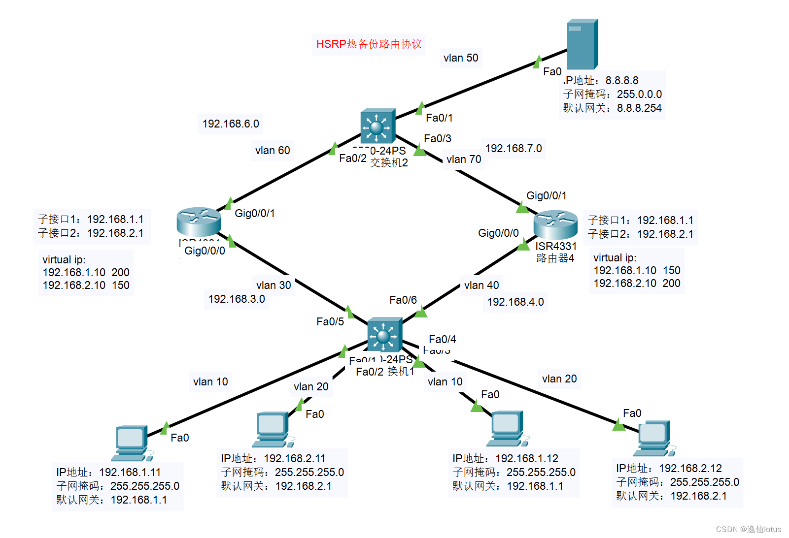
3、配置主机和服务器
规划主机IP地址
单击PC主机,选择桌面,单击IP配置,输入规划好的主机IP和默认网关,子网掩码会自动生成
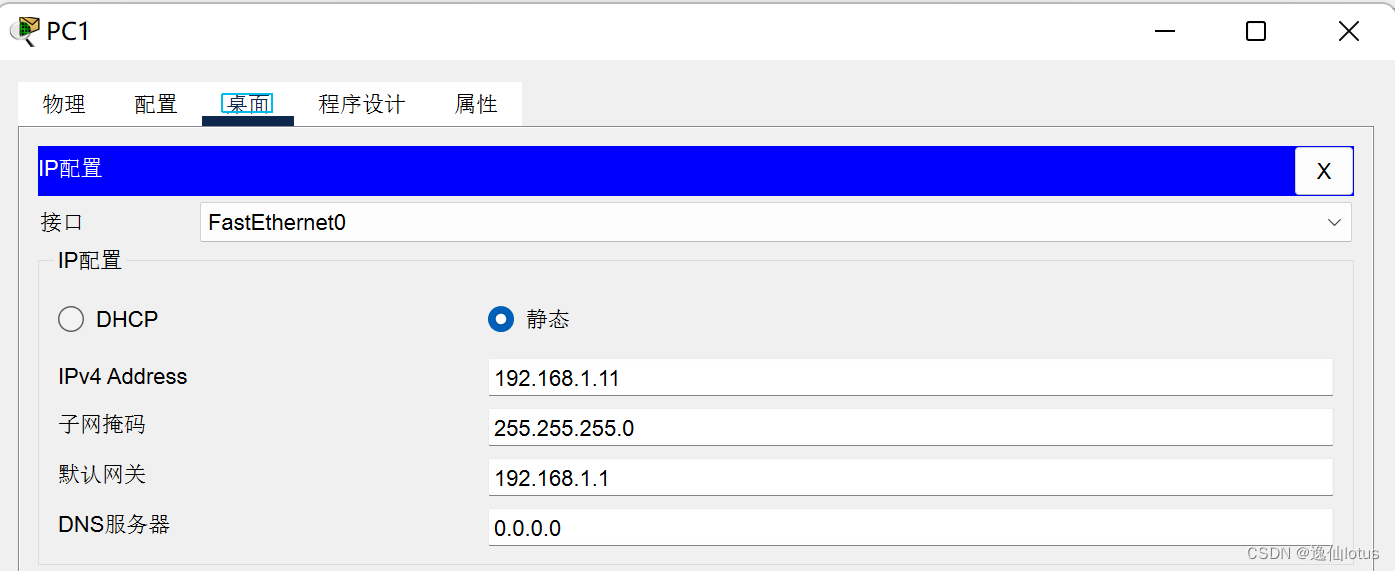
对PC2-PC4做相同配置
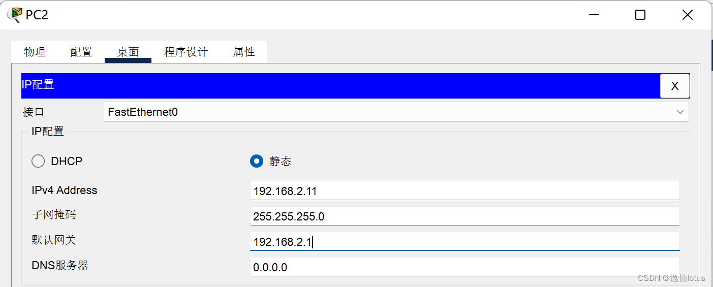
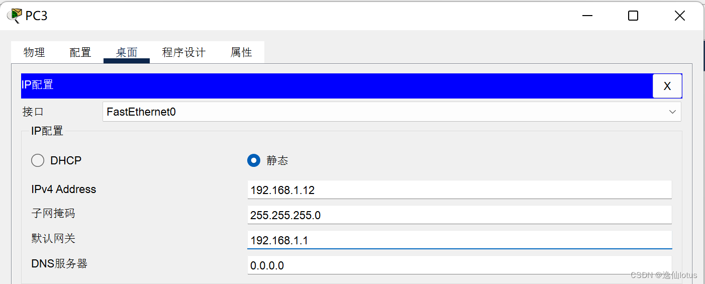
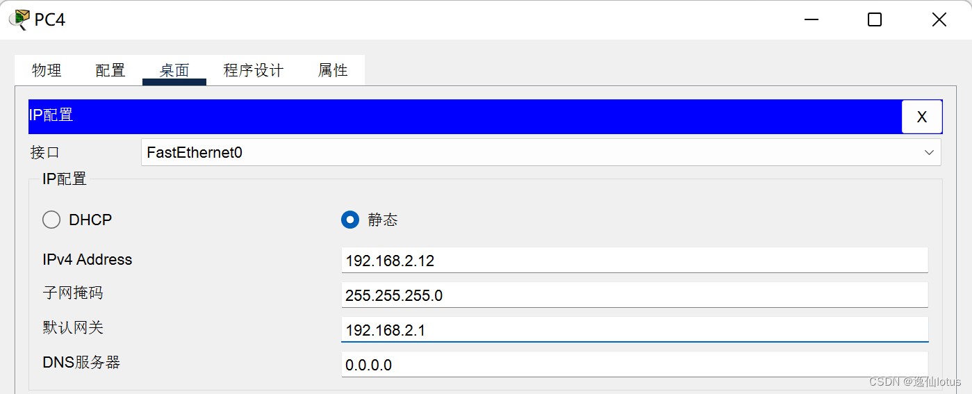
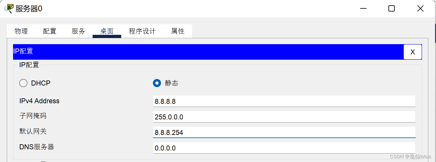
服务器IP地址进行一样的操作
4、配置交换机
配置交换机1,创建vlan10、20、30、40,vlan10和vlan20用于接入主机,交换方式设置为access
vlan30和vlan40用于连接路由器,交换方式设置为trunk
vlan相关配置完成后,接下来配置OSPF动态路由协议,将路由器划分到OSPF area 123
Switch>en
Switch#conf t
Enter configuration commands, one per line.  End with CNTL/Z.
Switch(config)#vlan 10
Switch(config-vlan)#name vlan10
Switch(config-vlan)#exit
Switch(config)#vlan 20
Switch(config-vlan)#name vlan20
Switch(config-vlan)#exit
Switch(config)#vlan 30
Switch(config-vlan)#name vlan30
Switch(config-vlan)#exit
Switch(config)#vlan 40
Switch(config-vlan)#name vlan40
Switch(config-vlan)#exitSwitch(config)#int f0/1
Switch(config-if)#switchport access vlan 10
Switch(config-if)#no shutdown
Switch(config-if)#exit
Switch(config)#int f0/2
Switch(config-if)#switchport access vlan 20
Switch(config-if)#no shutdown
Switch(config-if)#exit
Switch(config)#int f0/3
Switch(config-if)#switchport access vlan 10
Switch(config-if)#no shutdown
Switch(config-if)#exit
Switch(config)#int f0/4
Switch(config-if)#switchport access vlan 20
Switch(config-if)#no shutdown
Switch(config-if)#exitSwitch(config)#int f0/5
Switch(config-if)#switchport trunk all vlan 30
Switch(config-if)#switchport trunk all vlan add 10
Switch(config-if)#switchport trunk all vlan add 20
Switch(config-if)#no shutdown
Switch(config-if)#exitSwitch(config)#int f0/6
Switch(config-if)#switchport trunk all vlan 40
Switch(config-if)#switchport trunk all vlan add 10
Switch(config-if)#switchport trunk all vlan add 20
Switch(config-if)#no shutdown
Switch(config-if)#exitSwitch(config)#int vlan10
Switch(config-if)#ip address 192.168.1.1 255.255.255.0
Switch(config-if)#exitSwitch(config)#int vlan 20
Switch(config-if)#ip address 192.168.2.1 255.255.255.0
Switch(config-if)#exitSwitch(config)#int vlan 30
Switch(config-if)#ip address 192.168.3.1 255.255.255.0
Switch(config-if)#exitSwitch(config)#int vlan 40
Switch(config-if)#ip address 192.168.4.1 255.255.255.0
Switch(config-if)#exitSwitch(config)#ip routing
Switch(config)#router ospf 1
Switch(config-router)#network 192.168.1.0 0.0.0.255 area 123
Switch(config-router)#network 192.168.2.0 0.0.0.255 area 123
Switch(config-router)#network 192.168.3.0 0.0.0.255 area 123
Switch(config-router)#network 192.168.4.0 0.0.0.255 area 123
Switch(config-router)#end
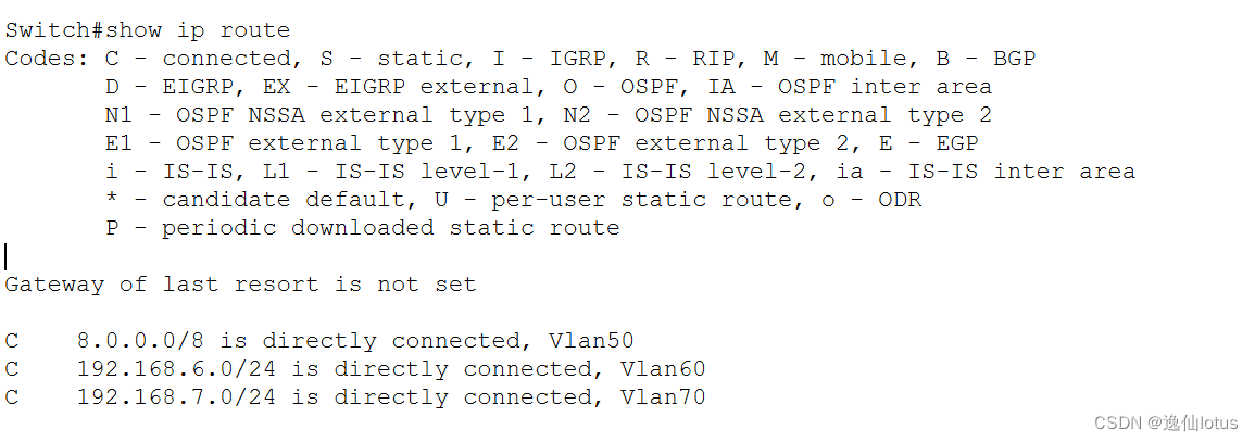
配置交换机2,创建vlan50、60、70,vlan 50用于连接服务器和交换机,交换方式也是access,vlan 60和vlan 70用于连接路由器和交换机,交换方式trunk,此处创建vlan以及vlan接入方式同上文。
Switch>enable
Switch#configure terminal
Enter configuration commands, one per line.  End with CNTL/Z.
Switch(config)#hostname Switch2Switch2(config)#vlan 50
Switch2(config-vlan)#name vlan50
Switch2(config-vlan)#exitSwitch2(config)#vlan 60
Switch2(config-vlan)#name vlan60
Switch2(config-vlan)#exitSwitch2(config)#vlan 70
Switch2(config-vlan)#name vlan70
Switch2(config-vlan)#exitSwitch2(config)#int f0/1
Switch2(config-if)#switchport access vlan 50
Switch2(config-if)#no shutdown
Switch2(config-if)#exitSwitch2(config)#int f0/2
Switch2(config-if)#no shutdown
Switch2(config-if)#switchport trunk all vlan 60
Switch2(config-if)#switchport trunk all vlan add 50
Switch2(config-if)#switchport trunk all vlan add 70
Switch2(config-if)#exitSwitch2(config)#int f0/3
Switch2(config-if)#no shutdown
Switch2(config-if)#switchport trunk all vlan 70
Switch2(config-if)#switchport trunk all vlan add 50
Switch2(config-if)#switchport trunk all vlan add 60
Switch2(config-if)#exitSwitch2(config)#int vlan 50
Switch2(config-if)#ip address 8.8.8.254 255.0.0.0
Switch2(config-if)#exitSwitch2(config)#int vlan 60
Switch2(config-if)#ip address 192.168.6.1 255.255.255.0
Switch2(config-if)#exitSwitch2(config)#int vlan 70
Switch2(config-if)#ip address 192.168.7.1 255.255.255.0
Switch2(config-if)#exitSwitch2(config)#ip routing
Switch2(config)#router ospf 1
Switch2(config-router)#network 8.0.0.0 255.255.255.0 area 123
Switch2(config-router)#network 192.168.6.0 0.0.0.255 area 123
Switch2(config-router)#network 192.168.7.0 0.0.0.255 area 123
Switch2(config-router)#exit
5、配置路由器
配置端口g0/0/0,设置该端口的IP地址,设置两个子接口192.168.1.10和192.168.2.10,每个子接口划分成组,配置虚拟网关,是否抢占,优先级
//进入全局配置模式,并修改路由器名称R1
Router>enable
Router#configure terminal
Enter configuration commands, one per line.  End with CNTL/Z.
Router(config)#hostname R1//配置子接口1,IP以及虚拟ip网关
R1(config)#int g0/0/0.1
R1(config-subif)#encapsulation dot1q 10
R1(config-subif)#ip address 192.168.1.1 255.255.255.0    //子接口IP地址
R1(config-subif)#standby 1 ip 192.168.1.10        //vlan10的虚拟网关
R1(config-subif)#standby 1 preempt            //设置为抢占模式
R1(config-subif)#standby 1 priority 200       //设置优先级为200
R1(config-subif)#exit//配置子接口2,IP以及虚拟ip网关
R1(config)#int g0/0/0.2
R1(config-subif)#encapsulation dot1q 20
R1(config-subif)#ip address 192.168.2.1 255.255.255.0
R1(config-subif)#standby 2 ip 192.168.2.10
R1(config-subif)#standby 2 preempt
R1(config-subif)#standby 2 priority 150
R1(config-subif)#exit//配置接口
R1(config)#int gigabitEthernet 0/0/1
R1(config-if)#ip address 192.168.6.2 255.255.255.0//ospf视图下发布直连路由
R1(config)#router ospf 1
R1(config-router)#network 192.168.3.0 0.0.0.255 area 123
R1(config-router)#network 192.168.6.0 0.0.0.255 area 123
R1(config-router)#exit
配置后查看路由表
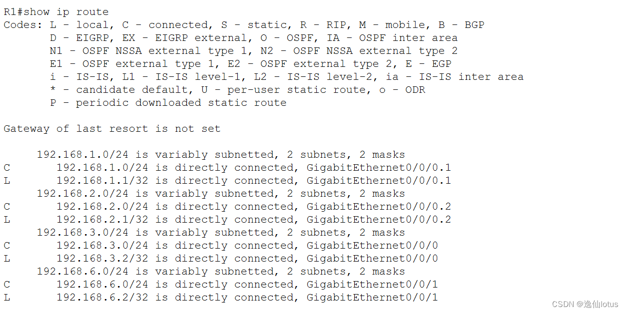
(另一台路由器做相同配置,注意划分网段和IP)
Router>enable
Router#configure  terminal
Enter configuration commands, one per line.  End with CNTL/Z.
Router(config)#hostname R2R2(config)#int g0/0/0.1
R2(config-subif)#encapsulation dot1q 10
R2(config-subif)#ip address 192.168.1.1 255.255.255.0
R2(config-subif)#standby 1 ip 192.168.1.10
R2(config-subif)#standby 1 preempt
R2(config-subif)#standby 1 priority 150
R2(config-subif)#exitR2(config)#int g0/0/0.2R2(config-subif)#encapsulation dot1q 20
R2(config-subif)#ip address 192.168.2.1 255.255.255.0
R2(config-subif)#standby 2 ip 192.168.2.10
R2(config-subif)#standby 2 preempt
R2(config-subif)#standby 2 priority 200
R2(config-subif)#exitR2(config)#int g0/0/0
R2(config-if)#no shutdown
R2(config-if)#ip address 192.168.4.2 255.255.255.0
R2(config-if)#exitR2(config)#int g0/0/1
R2(config-if)#no shutdown
R2(config-if)#ip address 192.168.7.1 255.255.255.0
R2(config-if)#exitR2(config)#router ospf 1
R2(config-router)#network 192.168.7.0 0.0.0.255 area 123
R2(config-router)#network 192.168.4.0 0.0.0.255 area 123
R2(config-router)#exit


