Arduino DC Motor Speed Control with Encoder, Arduino DC Motor Encoder
作者
- How to control dc motor with encoder:
- DC Motor with Encoder + Arduino, Circuit Diagram:
- Driving the Motor with Encoder and Arduino:
- Control DC motor using Encoder feedback loop:
How to control dc motor with encoder:
Arduino DC Motor Speed Control with Encoder- I have been using different types of stepper motors, Servo motors, and DC Motors for quite a long time in different intermediate and advanced level projects. DC motors are more frequently used than Stepper Motors and Servo Motors. If you have watched my videos and read my articles then you should know DC motors are quite different from Stepper Motors and servo Motors. These three types of motors have a different construction. The stepper motors and servo motors are designed in a way that we can control their position. We can control the steps in the forward and reverse directions. Servos can move from 0 to 180 degrees, so you can move to any position between 0 and 180. Likewise, in stepper motors, you can control the steps precisely and this is the reason stepper motors are used in CNC machines, 3d printers, etc.
使用编码器控制 Arduino 直流电机速度–我在不同的中高级项目中使用不同类型的步进电机、伺服电机和直流电机已经有很长一段时间了。 直流电机比步进电机和伺服电机更常用。 如果你看过我的视频和文章,就应该知道直流电机与步进电机和伺服电机有很大不同。 这三种电机的结构各不相同。 步进电机和伺服电机的设计方式使我们可以控制它们的位置。 我们可以控制步进的前进和后退方向。 舵机可以移动到 0 至 180 度之间的任何位置。 同样,步进电机可以精确控制步数,这也是步进电机被用于数控机床、3d 打印机等的原因。
On the other hand, when a dc motor is powered up it immediately starts rotating, it continuously rotates, you can’t exactly control its position until you use a specific technique. You can’t 100% control a DC motor like Stepper motor and Servo, but if you add an encoder it can really change the whole game. With an encoder being added, you can keep track of the motor revolutions, the amount of distance it has covered, and this way you can make a nice feedback system that can be used to control the DC motor. Then you can stop the DC motor at the position where you want it to stop. The control of a DC motor using an encoder is not that simple, you just simply can’t start by adding an encoder with the DC Motor and start controlling the DC motor, to use an encoder you will need a controller, the controller will read the encoder and then will accordingly control the DC motor as per the pre-defined instructions written by the programmer. for this project, you will need a microcontroller board like the Arduino Uno or Arduino Nano, or Arduino Mega, or Arduino pro mini, etc. I know beginners are more comfortable with Arduino Uno, Arduino mega, and Arduino Nano, so I will start with the Arduino Uno, the same connections and programs you can also try on Arduino Nano and Arduino Mega.
另一方面,直流电机通电后会立即开始旋转,并持续旋转,除非使用特定技术,否则无法准确控制其位置。 你无法像控制步进电机和伺服电机那样百分之百地控制直流电机,但如果添加一个编码器,就能真正改变整个游戏规则。 有了编码器,你就可以跟踪电机的转数和运行距离,这样你就可以建立一个很好的反馈系统,用来控制直流电机。 然后,你就可以让直流电机停在你希望它停的位置。 使用编码器控制直流电机并不那么简单,你不能一开始就在直流电机上添加一个编码器,然后开始控制直流电机,要使用编码器,你需要一个控制器,控制器将读取编码器,然后根据程序员编写的预定义指令相应地控制直流电机。 我知道初学者更喜欢 Arduino Uno、Arduino mega 和 Arduino Nano,所以我将从 Arduino Uno 开始,同样的连接和程序你也可以在 Arduino Nano 和 Arduino Mega 上尝试。
To get started, you will need Arduino Uno, a Motor driver, a DC Motor, and of course an Encoder. To read the Encoder, we will connect the encoder output pins with Arduino’s pins 2 and 3 which are the interrupt pins. The power wires of the encoder will be connected with the Arduino’s 5V and GND. To keep things simpler, I will start with the simple example code in which I will use pins 2 and 3 as the normal digital pins, we won’t activate the interrupts and then in the second example code, we will use the interrupts. Without any further delay, let’s get started!!!
要开始使用,您需要 Arduino Uno、一个电机驱动器、一个直流电机,当然还有一个编码器。 为了读取编码器,我们将把编码器的输出引脚与 Arduino 的中断引脚 2 和 3 连接起来。 编码器的电源线将与 Arduino 的 5V 和 GND 连接。 为了简化操作,我将从简单的示例代码开始,其中我将把引脚 2 和 3 用作普通的数字引脚,我们不会激活中断,然后在第二个示例代码中,我们将使用中断。 事不宜迟,让我们开始吧
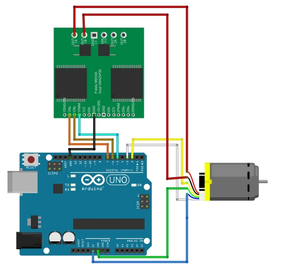
DC Motor with Encoder + Arduino, Circuit Diagram:
The type of the DC motor as you can see in the circuit diagram given below has a built-in encoder. So, it’s totally up to you whether you want to use it as the simple dc motor or you want to use the encoder, or you can use the motor and encoder together at the same time. As you can see in the circuit diagram, the power wires which are the Red and Black wires are not connected but the encoder wires are connected. For this first example, we will only be using the encoder to understand the basics this way you will easily understand how an encoder works. So, we will rotate the motor shaft by hand to see the trigger signals.
从下面的电路图中可以看到,这种直流电机内置了编码器。 因此,你完全可以决定是将其用作简单的直流电机,还是使用编码器,或者同时使用电机和编码器。 如电路图所示,电源线(红线和黑线)没有连接,但编码器线已经连接。 在第一个示例中,我们将只使用编码器来了解基础知识,这样你就会很容易理解编码器的工作原理。 因此,我们将用手旋转电机轴来查看触发信号。

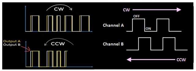
An encoder works by observing changes to the magnetic field created by a magnet attached to the motor shaft, as the motor rotates the encoder outputs will trigger periodically. When the magnet spins clockwise, output “a” will trigger first, and when rotated counterclockwise on the other hand output “b” will trigger. This way you know exactly which way the motor shaft is rotating. This can be quite handy in situations where you need to control the forward and reverse movement of the DC Motor.
编码器的工作原理是观察连接在电机轴上的磁铁所产生的磁场变化,当电机旋转时,编码器输出将周期性地触发。 当磁铁顺时针旋转时,输出端 "a "将首先触发,反之,当逆时针旋转时,输出端 "b "将触发。 这样,您就能准确知道电机轴的旋转方向。 在需要控制直流电机正反转的情况下,这将非常方便。
Let’s write a very simple program to understand how an encoder works and how to read the encoder outputs.
让我们编写一个非常简单的程序,了解编码器的工作原理以及如何读取编码器的输出。
Arduino Encoder Code:
#define ENCA 2 // pin2 of the Arduino
#define ENCB 3 // Pin3 of the Arduino
int ENCA_DATA;
int ENCB_DATA;void setup() {Serial.begin(9600); // Activates Serial communicationpinMode(ENCA,INPUT); // sets pin2 as the inputpinMode(ENCB,INPUT); // sets pin3 as the input
}void loop() {ENCA_DATA = digitalRead(ENCA);
// We simply read Pin2 of the Arduino and store the result in variable ENCA_DATAENCB_DATA = digitalRead(ENCB);
// We simply read Pin3 of the Arduino and store the result in variable bSerial.print(ENCA_DATA*5); Serial.print(" ");Serial.print(ENCB_DATA*5);Serial.println();
}
Arduino Encoder Code Explanation:
We don’t need any libraries for this basic program. First of all, I started off by defining the Arduino pins 2 and 3. I will call these pins the ENCA and ENCB. These two pins will be connected with the Encoder outputs.
Next, I defined two variables ENCA_DATA and ENCB_DATA.
这个基本程序不需要任何库。 首先,我定义了 Arduino 的 2 号和 3 号引脚。 我将这两个引脚称为 ENCA 和 ENCB。 接下来,我定义了两个变量 ENCA_DATA 和 ENCB_DATA。
#define ENCA 2
#define ENCB 3int ENCA_DATA;
int ENCB_DATA;
Next, we will need to tell the Arduino whether we want to use the Serial communication? And the pins we just defined are going to be used as the inputs or outputs? All this is done in the void setup() function.
接下来,我们需要告诉 Arduino 是否要使用串行通信? 我们刚刚定义的引脚将用作输入还是输出? 所有这些都将在 void setup() 函数中完成。
void setup() {Serial.begin(9600);pinMode(ENCA,INPUT);pinMode(ENCB,INPUT);}
In the void setup() function, I simply activated the serial communication and I selected 9600 as the Baud rate. Next, I set the two pins ENCA and ENCB as the inputs using the pinMode() functions.
The void setup() function executes only once with the Arduino board is first turned ON. The actual code is placed inside the loop() function which executes repeatedly.
在 void setup() 函数中,我只需激活串行通信,并选择 9600 作为波特率。 接下来,我使用 pinMode() 函数将两个引脚 ENCA 和 ENCB 设置为输入。 void setup() 函数只在 Arduino 板首次打开时执行一次。 实际代码放在loop()函数中重复执行。
void loop() {ENCA_DATA = digitalRead(ENCA);ENCB_DATA = digitalRead(ENCB);
I simply defined a variable “ENCA_DATA” which is of the type integer. Then we read the ENCA pin using the digitalRead() function and store the value in variable ENCA_DATA, exactly the same thing I did for the ENCB.
我们使用 digitalRead() 函数读取 ENCA 引脚,并将值存储到变量 ENCA_DATA,在 ENCB 上所做的完全相同。
Serial.print(ENCA_DATA*5);Serial.print(” “);Serial.print(ENCB_DATA*5);Serial.println();}
Next, to write outputs to the computer screen I used the Serial.print() and Serial.println() functions. Inside the parenthesis, you can see I am multiplying the values by 5 to make the plot easier to read.
All you need is to compile the code first to check if any keywords are misspelled, and then you can upload the code.
After the code has been uploaded, you can go ahead and open the Serial Monitor and select the 9600 Baud Rate. Now, you can start by rotating the DC Motor shaft which has the encoder. The Encode signal changes as you rotate the motor shaft, these changes are easier to understand with the serial plotter. So, output “a” is triggered when you rotate the shaft Clockwise and similarly, the output “b” is triggered when you rotate the shaft anti-clockwise. This code has nothing to do with the motor shaft position, the purpose of this code was just to help you understand how these two outputs “a” and “b” are triggered.
Now let’s measure the position of the DC motor shaft. Nothing is changed on the hardware side. We are using the same connections.
接下来,为了将输出写入电脑屏幕,我使用了 Serial.print() 和 Serial.println() 函数。 在括号内,你可以看到我将数值乘以 5,以便更容易读取图表。 你只需要先编译代码,检查是否有关键字拼错,然后就可以上传代码了。 代码上传后,你可以继续打开串行监视器,选择 9600 波特率。 现在,你可以开始旋转带有编码器的直流电机轴。 编码器信号会随着电机轴的旋转而变化,使用串行绘图仪更容易理解这些变化。 因此,顺时针旋转电机轴时,输出 "a "被触发;同样,逆时针旋转电机轴时,输出 "b "被触发。 这段代码与电机轴的位置无关,其目的只是帮助你理解这两个输出 "a "和 "b "是如何触发的。 现在我们来测量直流电机轴的位置。 硬件方面没有任何变化。 我们使用的是相同的连接。
Position of the encoder Arduino Code:
#include <Arduino.h>#define Encoder_output_A 2 // pin2 of the Arduino
#define Encoder_output_B 3 // pin 3 of the Arduino
// these two pins has the hardware interrupts as well.int Count_pulses = 0;void DC_Motor_Encoder();
void setup()
{Serial.begin(9600);               // activates the serial communicationpinMode(Encoder_output_A, INPUT); // sets the Encoder_output_A pin as the inputpinMode(Encoder_output_B, INPUT); // sets the Encoder_output_B pin as the inputattachInterrupt(digitalPinToInterrupt(Encoder_output_A), DC_Motor_Encoder, RISING);
}void loop()
{Serial.println("Result: ");Serial.println(Count_pulses);
}void DC_Motor_Encoder()
{int b = digitalRead(Encoder_output_B);if (b > 0){Count_pulses++;}else{Count_pulses--;}
}
Position of the encoder Arduino Code Explanation:
This code is the modified version of the code that I just explained above. I made some changes, which I am sure you can clearly see. Let’s talk about these changes in detail. The pins 2 and 3 connections remain exactly the same.
这段代码是我上面解释过的代码的修改版。 做了一些改动,让我们来详细谈谈这些改动。 引脚 2 和引脚 3 的连接方式保持不变。
#define Encoder_output_A 2 // pin2 of the Arduino
#define Encoder_output_B 3 // pin 3 of the Arduino
// these two pins has the hardware interrupts as well.
I defined a global variable Count_pulses and initially stored a value of 0 in it. As this is a global variable so I can access this variable from anywhere inside my Arduino code.
我定义了一个全局变量 Count_pulses,初始值为 0。 由于这是一个全局变量,因此我可以从 Arduino 代码的任何地方访问该变量。
int Count_pulses = 0;
Inside the void setup() function, you can clear see the first three lines of code are exactly the same.
void setup() {
Serial.begin(9600); // activates the serial communication
pinMode(Encoder_output_A,INPUT); // sets the Encoder_output_A pin as the input
pinMode(Encoder_output_B,INPUT); // sets the Encoder_output_B pin as the input
attachInterrupt(digitalPinToInterrupt(Encoder_output_A),DC_Motor_Encoder,RISING);
}
This time I added this attachInterrupt(digitalPinToInterrupt(Encoder_output_A),DC_Motor_Encoder,RISING); this line of code. The attachinterrupt() function is used to activate the hardware interrupt. The attachinterrupt() function takes three arguments as the input. The first one is the pin digitalPinToInterrupt(Encoder_output_A), the second argument is the function name, this function will execute each time when an interrupt happens on the Encoder_output_A pin of the Arduino which is pin 2. The 3rd argument is to tell whether to take action on the rising edge or the falling edge. So, our interrupt setting is completed.
This time inside the loop function many things are changed. This time inside the loop() function we are only using 2 lines of code, the first line of code prints the text Result and the “Serial.println(Count_pulses);” which prints the value stored in the variable Count_pulses.
这次我添加了attachInterrupt(digitalPinToInterrupt(Encoder_output_A),DC_Motor_Encoder,RISING);这行代码。 attachinterrupt() 函数用于激活硬件中断。 attachinterrupt() 函数将三个参数作为输入。 第一个参数是引脚 digitalPinToInterrupt(Encoder_output_A),第二个参数是函数名称,每次当 Arduino 的Encoder_output_A引脚(即引脚 2)发生中断时,该函数就会执行。 第三个参数是告诉我们是在上升沿还是下降沿采取行动。 这样,我们的中断设置就完成了。我们在 loop() 函数中只使用了两行代码,第一行代码打印文本 Result 和 “Serial.println(Count_pulses);”,后者打印存储在变量 Count_pulses 中的值。
void loop() {
Serial.println(“Result: “);
Serial.println(Count_pulses);
}
DC_Motor_Encoder() function is a user-defined function it has no return type and does not take any arguments as the input. This is the function that is executed when an interrupt happens on pin2 of the Arduino. So, inside this function we are simply reading the Encoder_output_B pin, the value is stored in variable b. Next, we use an if condition to check if a signal is detected then increment the Count_pulses by 1 or else decrement the Count_pulses.
DC_Motor_Encoder() 函数是一个用户自定义函数,它没有返回类型,也不将任何参数作为输入。 当 Arduino 的引脚 2 发生中断时,该函数将被执行。 因此,在该函数中,我们只需读取 Encoder_output_B 引脚的值,并将其存储在变量 b 中。接下来,我们使用 if 条件来检查是否检测到信号,然后将 Count_pulses 递增 或递减 。
void DC_Motor_Encoder(){
int b = digitalRead(Encoder_output_B);
if(b > 0){
Count_pulses++;
}
else{
Count_pulses–;
}
}
Upload the code, open the serial monitor, and start rotating the encoder. Rotate the motor shaft in the clockwise direction and also in the anti-clockwise direction. In one direction the value will increase and in the other direction the value will decrease.
上传代码,打开串行监视器,开始旋转编码器。 顺时针和逆时针旋转电机轴。 在一个方向上,数值会增加,在另一个方向上,数值会减少。
Driving the Motor with Encoder and Arduino:
Now, I am sure you have completely understood how an Encoder works, how the Encoder outputs are triggered, and then how to write a simple code to count the pulses. So far we were manually rotating the DC motor shaft to trigger the Encoder outputs, now to do everything automatically it’s time to connect a motor driver so that we can read the position measurements from the Encoder. Start by connecting the DC motor wires to the outputs of the motor driver circuit. The motor driver also needs an appropriate power supply, which you will need to select as per your DC motor specs. Next, connect the Motor driver ground to the Arduino ground, the PWM input of the motor driver should be connected to an Arduino PWM pin here I have used pin 5.
现在,我相信你已经完全了解了编码器的工作原理、编码器输出的触发方式以及如何编写简单的代码来计数脉冲。 到目前为止,我们都是通过手动旋转直流电机轴来触发编码器输出,现在要想自动完成所有操作,就需要连接电机驱动器,以便读取编码器的位置测量值。 首先将直流电机导线连接到电机驱动器电路的输出端。 电机驱动器还需要适当的电源,您需要根据直流电机的规格来选择。 接下来,将电机驱动器的地线连接到 Arduino 的地线上,电机驱动器的 PWM 输入应连接到 Arduino 的 PWM 引脚上,这里我使用的是第 5 引脚。
The other two motor driver pins can be connected to any of the remaining Arduino digital pins. Before writing the control algorithm, Let’s test the motor driver start by defining the pins that you connected to the motor driver.
另外两个电机驱动器引脚可以连接到 Arduino 其余的任何数字引脚上。 在编写控制算法之前,让我们先测试一下电机驱动器,定义连接到电机驱动器的引脚。
Driving the Motor with Encoder, Arduino Code:
#include <Arduino.h>#define ENCA 2
#define ENCB 3
#define PWM 5
#define IN2 6
#define IN1 7int pos = 0;void setMotor(int dir, int pwmVal, int pwm, int in1, int in2);
// void setMotor(int, int, int, int, int);
void readEncoder();void setup()
{Serial.begin(9600);pinMode(ENCA, INPUT);pinMode(ENCB, INPUT);attachInterrupt(digitalPinToInterrupt(ENCA), readEncoder, RISING);
}void loop()
{setMotor(1, 25, PWM, IN1, IN2);delay(200);Serial.println(pos);setMotor(-1, 25, PWM, IN1, IN2);delay(200);Serial.println(pos);setMotor(0, 25, PWM, IN1, IN2);delay(20);Serial.println(pos);
}void setMotor(int dir, int pwmVal, int pwm, int in1, int in2)
{analogWrite(pwm, pwmVal);if (dir == 1){digitalWrite(in1, HIGH);digitalWrite(in2, LOW);}else if (dir == -1){digitalWrite(in1, LOW);digitalWrite(in2, HIGH);}else{digitalWrite(in1, LOW);digitalWrite(in2, LOW);}
}void readEncoder()
{int b = digitalRead(ENCB);if (b > 0){pos++;}else{pos--;}
}
It is useful to define a function that will set the motor direction and speed. The interface for the setMotor function, I have written here sets the direction and speed of a motor with the pins defined in the last three inputs. Inside the function, I have set the speed with an analog write command. if the direction integer is 1 then the motor will rotate one way by writing a high low combination to the input pins of the driver. If you reverse the order to a low-high combination the motor will rotate in the other direction. Inside the loop function, you can call the setMotor function to drive the motor also write the position to the serial line.
定义一个可以设置电机方向和速度的函数非常有用。 我在这里编写的 setMotor 函数接口使用最后三个输入中定义的引脚来设置电机的方向和速度。 如果方向整数为 1,那么通过向驱动器的输入引脚写入高-低组合,电机将单向旋转。 如果将顺序颠倒为低-高组合,电机将向另一个方向旋转。 在循环函数中,可以调用 setMotor 函数来驱动电机,同时将位置写入串行线。
Control DC motor using Encoder feedback loop:
So far we have connected the controller motor driver and motor in a loop but we have not used the position signal from the encoder to control the motor position. We will use a feedback loop. In a feedback loop the control components are often referred to as the plant(motor) here that is the motor and the motor driver. The sensor(encoder) that we are using to measure position is the encoder. In order to actually control the position of the motor you need to provide it with a target position, then you take the difference between the target position and the measured position, the result is the error usually written as e(t).
到目前为止,我们已将控制器电机驱动器和电机连接成一个环路,但还没有使用编码器的位置信号来控制电机位置。 我们将使用反馈回路。 在反馈回路中,控制部件通常被称为设备(电机),这里指的是电机和电机驱动器。 我们用来测量位置的传感器(编码器)就是编码器。 为了实际控制电机的位置,需要为其提供一个目标位置,然后求出目标位置与测量位置之间的差值,其结果就是误差,通常写为 e(t)。

Now that the error has been computed you can use a controller to compute a control signal that is sent to the plant(motor). The control signal is configured so that it will attempt to reduce the error. The control signal is typically written as u(t).
In this project, we will use the PID control algorithm to generate the control signal u(t) the PID control signal is constructed using a sum of three terms a proportional, derivative, and integral term that is what PID stands for. The proportional term is the most important as it is directly responsible for reducing the error, the derivative and integral terms are typically used to smooth out the control system response. The three constants kp, ki and kd determine how strongly each term is represented in the control loop; you can adjust these constants to tune your response. You can estimate the integral and derivative of the error using the simple finite difference approximation. The integral term accumulates the error over time and the derivative computes how quickly the error is changing with the feedback control loop. Complete, you’re ready to write code to control the position of the motor.
既然误差已经计算出来,那么就可以使用控制器来计算发送给设备(电机)的控制信号。 控制信号经过配置后,来减小误差。 在本项目中,我们将使用 PID 控制算法来生成控制信号 u(t)。PID 控制信号由比例项、导数项和积分项三个项的总和构成,这就是 PID 的含义。 比例项最为重要,因为它直接负责减少误差,而导数和积分项通常用于平滑控制系统的响应。 三个常数 kp、ki 和 kd 决定了每个项在控制回路中的体现程度;您可以调整这些常数来调整响应。 您可以使用简单的有限差分近似估算误差的积分和导数。 积分项计算误差随时间的累积,导数项计算误差随反馈控制回路变化的速度。 完成后,您就可以编写代码来控制电机的位置了。
DC Motor control with Encoder Feedback, Arduino Code:
#include <Arduino.h>#define ENCA 2
#define ENCB 3
#define PWM 5
#define IN2 6
#define IN1 7int pos = 0;
long prevT = 0;
float eprev = 0;
float eintegral = 0;void setMotor(int dir, int pwmVal, int pwm, int in1, int in2);
void readEncoder();void setup()
{Serial.begin(9600);pinMode(ENCA, INPUT);pinMode(ENCB, INPUT);attachInterrupt(digitalPinToInterrupt(ENCA), readEncoder, RISING);Serial.println("target pos");
}void loop()
{// set target positionint target = 1200;// target = 250*sin(prevT/1e6);// PID constantsfloat kp = 1;float kd = 0.025;float ki = 0.0;// time differencelong currT = micros();float deltaT = ((float)(currT - prevT)) / (1.0e6);prevT = currT;// errorint e = pos - target;// derivativefloat dedt = (e - eprev) / (deltaT);// integraleintegral = eintegral + e * deltaT;// control signalfloat u = kp * e + kd * dedt + ki * eintegral;// motor powerfloat pwr = fabs(u);if (pwr > 255){pwr = 255;}// motor directionint dir = 1;if (u < 0){dir = -1;}// signal the motorsetMotor(dir, pwr, PWM, IN1, IN2);// store previous erroreprev = e;Serial.print(target);Serial.print(" ");Serial.print(pos);Serial.println();
}void setMotor(int dir, int pwmVal, int pwm, int in1, int in2)
{analogWrite(pwm, pwmVal);if (dir == 1){digitalWrite(in1, HIGH);digitalWrite(in2, LOW);}else if (dir == -1){digitalWrite(in1, LOW);digitalWrite(in2, HIGH);}else{digitalWrite(in1, LOW);digitalWrite(in2, LOW);}
}void readEncoder()
{int b = digitalRead(ENCB);if (b > 0){pos++;}else{pos--;}
}
Start by defining global storage variables that can be used to save values between time steps, these are used in the finite difference estimates for the integral and derivative. The first thing that you need to do in the loop function is set a target for the control loop; the control signal will be adjusted over time as the measured position becomes closer to the target. Next, define the constants used in the PID control algorithm start by setting kp to 1 and kd and ki to 0. you can come back and adjust these later to compute the finite difference approximations. We need to compute the time difference t start by recording the current time in microseconds using the micros function then compute t in seconds by taking the difference between the current time and the previous time, be careful that you are performing floating-point arithmetic not integer arithmetic; complete the calculation by storing the current time in the previous time variable for use.
首先要定义全局存储变量,用于保存周期内的值,这些值将用于积分和导数的有限差分估算。 在loop()函数中需要做的第一件事是为控制环路设置一个目标值;当测量位置变得更接近目标值时,控制信号将随时间而调整。 接下来,定义 PID 控制算法中使用的常数,将 kp 设为 1,kd 和 ki 设为 0。 我们需要计算时间差 t,首先使用 micros() 函数记录当前时间(以微秒为单位),然后计算当前时间与前一时间的差值(以秒为单位),注意是浮点运算而不是整数运算;完成计算后,将当前时间存储到前一时间变量中备用。
In the next iteration of the loop, the error is computed as the difference between the target and measured positions here I have reversed the order because of the way that I wired the motor leads if you find that your control algorithm is not working you can try switching the sign of the error term as I did now compute the derivative and integral of the arrow signal using the finite difference approximations with all that work done you are finally ready to compute your control signal. it is surprisingly simple is not it this signal will tell the plant the direction and speed to turn the motor to send the signal to the motor. We need to convert it into a speed and direction start by computing the PWM signal as the floating-point absolute value of the control signal U.
在循环的下一次迭代中,误差被计算为目标位置和测量位置之间的差值。在这里,由于电机引线的接线方式不同,我将顺序颠倒了一下,如果您发现控制算法不起作用,可以尝试像我一样转换误差项的符号。 这个信号将告诉工厂电机的旋转方向和速度,并将信号发送给电机。 我们需要通过计算 PWM 信号作为控制信号 U 的浮点绝对值,将其转换为速度和方向起始信号。
You also need to cap the PWM signal at 255 as that is the maximum value we can write next to determine the direction by computing the sign of the control signal u with the motor speed and direction computed from the control signal call the setMotor function to write to the motor driver to complete the loop function store the previous value of the error also print your target and measure positions to the serial com, so you can test how well your control algorithm is performing with these parameters. I am seeing a little overshoot after reaching the target. In other words, the motor spins too far and has to reverse directions to achieve the target position one way to reduce overshoot is to increase the derivative term here I have set kd equal to 0.025 this is enough to completely remove the overshoot for this system. Once your system works to achieve a constant target try setting a target that changes with time here I have set a sinusoidal target depending on your target and loading conditions you will need to further tune your PID parameters.
此外,您还需要将 PWM 信号的上限设定为 255,因为这是我们可以写入的最大值。接下来,通过计算控制信号 u 的符号以及从控制信号中计算出的电机速度和方向来确定方向,调用 setMotor 函数写入电机驱动器,以完成循环功能,存储之前的误差值,并将目标位置和测量位置打印到串行通信端口,这样您就可以测试您的控制算法在使用这些参数时的性能如何。 在达到目标位置后,我看到了一点过冲。 换句话说,电机转得太快,必须反转方向才能达到目标位置。减少过冲的方法之一是增加导数项,在这里我将 kd 设为 0.025,这足以完全消除该系统的过冲。 一旦您的系统能够实现恒定目标,请尝试设置一个随时间变化的目标,在这里我设置了一个正弦目标,具体取决于您的目标和负载条件,您需要进一步调整 PID 参数。