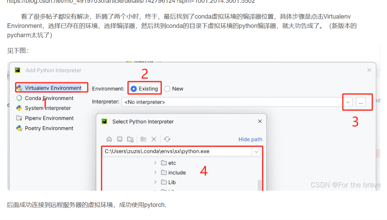
一.实验拓扑:
 二.实验需求:
1.内网Ip地址使用172.16.0.0/分配
2.sw1和SW2之间互为备份
3.VRRP/STP/VLAN/Eth-trunk均使用
4.所有Pc均通过DHCP获取IP地址
5.ISP只能配置IP地址
6.所有电脑可以正常访问IsP路由器环回
三.实验步骤---思路
1.首先,IP 地址规划要确保使用 172.16.0.0/12,需要合理分配子网。例如,VLAN2 和 VLAN3 可以使用 172.16.2.0/24 和 172.16.3.0/24。AR1 与 SW1、SW2 的连接可能需要单独的子网,比如 172.16.0.0/30 和 172.16.0.4/30。
2.然后,VLAN 划分方面,SW3 和 SW4 的 PC 接口需要分别加入 VLAN2 和 VLAN3。交换机间的连接使用 Trunk,并配置 Eth-trunk 聚合链路,提高带宽和冗余。
3.VRRP 配置在 SW1 和 SW2 的 VLAN 接口上,设置虚拟 IP 作为默认网关,优先级不同以实现主备切换。STP 启用 MSTP,防止环路,同时配置区域和实例。
4.DHCP 服务在 SW1 上配置,为 VLAN2 和 VLAN3 提供地址池。AR1 配置接口 IP 和环回地址,设置静态路由指向内网。SW1 和 SW2 配置默认路由指向 AR1。
5.测试部分需要验证 IP 获取、连通性、冗余切换和 STP 功能。需要确保所有步骤的代码正确,设备名称和接口名称准确,特别是 SW3 和 SW4 的连接。
6.最后,检查所有配置是否每一个条件,确保没有遗漏。例如,ISp 只能配置 IP 地址,所以不需要其他复杂配置。冗余链路和 Eth-trunk 的配置要正确,避免环路。
三.实验步骤---配置
1.创建VLAN
- 在 SW1、SW2、SW3、SW4 上创建 VLAN2 和 VLAN3。
[SW1]vlan batch 2 3  // 在 SW1 上批量创建 VLAN2 和 VLAN3
[SW2]vlan batch 2 3
[SW3]vlan batch 2 3
[SW4]vlan batch 2 3
2.Eth - trunk 配置
- 在 SW1 和 SW2 上创建 Eth - trunk 接口,并将它们之间互联的物理接口加入其中,实现链路聚合。
[SW1]interface Eth-Trunk 1
[SW1-Eth-Trunk1]mode lacp-static
[SW1-Eth-Trunk1]trunkport GigabitEthernet0/0/1 to GigabitEthernet0/0/2
[SW1-Eth-Trunk1]port link-type trunk
[SW1-Eth-Trunk1]port trunk allow-pass vlan 2 3[SW2]interface Eth-Trunk 1
[SW2-Eth-Trunk1]mode lacp-static
[SW2-Eth-Trunk1]trunkport GigabitEthernet0/0/1 to GigabitEthernet0/0/2
[SW2-Eth-Trunk1]port link-type trunk
[SW2-Eth-Trunk1]port trunk allow-pass vlan 2 3
3. VLAN 配置
- 将连接 PC1 和 PC3 的接口设置为 access 模式并加入 VLAN2;将连接 PC2 和 PC4 的接口设置为 access 模式并加入 VLAN3。
SW3:
interface GigabitEthernet0/0/1  // PC1接口
port link-type access
port default vlan 2
interface GigabitEthernet0/0/2  // PC2接口
port link-type access
port default vlan 3SW4:
interface GigabitEthernet0/0/1  // PC3接口
port link-type access
port default vlan 2
interface GigabitEthernet0/0/2  // PC4接口
port link-type access
port default vlan 3- 把交换机之间互联的接口设置为 trunk 模式,允许 VLAN2 和 VLAN3 的数据通过。
SW1:
interface GigabitEthernet0/0/3  // 连接SW3
port link-type trunk
port trunk allow-pass vlan 2 3
interface GigabitEthernet0/0/4  // 连接SW4
port link-type trunk
port trunk allow-pass vlan 2 3SW2:
interface GigabitEthernet0/0/4  // 连接SW3
port link-type trunk
port trunk allow-pass vlan 2 3
interface GigabitEthernet0/0/3  // 连接SW4
port link-type trunk
port trunk allow-pass vlan 2 3SW3:
interface GigabitEthernet0/0/3  // 连接SW1
port link-type trunk
port trunk allow-pass vlan 2 3
interface GigabitEthernet0/0/4  // 连接SW2
port link-type trunk
port trunk allow-pass vlan 2 3SW4:
interface GigabitEthernet0/0/4  // 连接SW1
port link-type trunk
port trunk allow-pass vlan 2 3
interface GigabitEthernet0/0/3  // 连接SW2
port link-type trunk
port trunk allow-pass vlan 2 3
4. STP 配置
- 在 SW1、SW2、SW3、SW4 上启用 STP 协议,选择合适的生成树模式( MSTP),防止网络中出现环路。
[SW1]stp mode mstp
[SW1]stp region-configuration
[SW1-mst-region]region-name STP-REGION
[SW1-mst-region]revision-level 1
[SW1-mst-region]instance 1 vlan 2
[SW1-mst-region]instance 2 vlan 3
[SW1-mst-region]active region-configuration[SW2]stp mode mstp
[SW2]stp region-configuration
[SW2-mst-region]region-name STP-REGION
[SW2-mst-region]revision-level 1
[SW2-mst-region]instance 1 vlan 2
[SW2-mst-region]instance 2 vlan 3
[SW2-mst-region]active region-configuration[SW3]stp mode mstp
[SW3]stp region-configuration
[SW3-mst-region]region-name STP-REGION
[SW3-mst-region]revision-level 1
[SW3-mst-region]instance 1 vlan 2
[SW3-mst-region]instance 2 vlan 3
[SW3-mst-region]active region-configuration[SW4]stp mode mstp
[SW4]stp region-configuration
[SW4-mst-region]region-name STP-REGION
[SW4-mst-region]revision-level 1
[SW4-mst-region]instance 1 vlan 2
[SW4-mst-region]instance 2 vlan 3
[SW4-mst-region]active region-configuration 
-
交换机1做组1的主根,做组2的备份根。交换机2做组2的主根,做组1的备份根
[sw1]stp instance 1 root primary
[sw1]stp instance 2 root secondary    [sw2]stp instance 1 root secondary
[sw2]stp instance 2 root primary
5.SVI配置
- SW1 和 SW2 上为 VLAN 2 和 VLAN 3 创建 SVI 接口,并配置 IP 地址
[SW1]interface Vlanif 2
[SW1-Vlanif2]ip address 172.16.2.1 255.255.255.0[SW1]interface Vlanif 3
[SW1-Vlanif3]ip address 172.16.3.1 255.255.255.0[SW2]interface Vlanif 2
[SW2-Vlanif2]ip address 172.16.2.2 255.255.255.0[SW2]interface Vlanif 3
[SW2-Vlanif3]ip address 172.16.3.2 255.255.255.0
6.VRRP 配置
- 分别为 Vlanif2 和 Vlanif3 配置 VRRP,设置虚拟 IP 地址,同时为 SW1 和 SW2 分配不同优先级,实现主备冗余。
[SW1]interface Vlanif 2
[SW1-Vlanif2]vrrp vrid 1 virtual-ip 172.16.2.254
[SW1-Vlanif2]vrrp vrid 1 priority 110
[SW1-Vlanif2]vrrp vrid 1 track int g0/0/1 reduced 11
[SW1-Vlanif2]dhcp select relay
[SW1-Vlanif2]dhcp relay server-ip 172.16.0.1[SW1]interface Vlanif 3
[SW1-Vlanif3]vrrp vrid 2 virtual-ip 172.16.3.254
[SW1-Vlanif3]dhcp select relay
[SW1-Vlanif3]dhcp relay server-ip 172.16.0.1[SW2]interface Vlanif 2
[SW2-Vlanif2]vrrp vrid 1 virtual-ip 172.16.2.254
[SW2-Vlanif2]dhcp select relay
[SW2-Vlanif2]dhcp relay server-ip 172.16.0.1[SW2]interface Vlanif 3
[SW2-Vlanif3]vrrp vrid 2 virtual-ip 172.16.3.254
[SW2-Vlanif3]vrrp vrid 2 priority 110
[SW2-Vlanif3]vrrp vrid 2 track int g0/0/1 reduced 11
[SW2-Vlanif3]dhcp select relay
[SW2-Vlanif3]dhcp relay server-ip 172.16.0.1 
7. DHCP 配置
- 为 VLAN2 和 VLAN3 分别创建 DHCP 地址池,指定网段、网关和 DNS 服务器地址,使 PC 能自动获取 IP 地址。
# 开启 DHCP 服务
[SW1] dhcp enable
# 创建 VLAN 2 的 DHCP 地址池
[SW1] ip pool vlan2_pool
# 配置可分配的 IP 地址范围
[SW1-ip-pool-vlan2_pool] network 172.16.2.0 mask 255.255.255.0
# 配置网关地址
[SW1-ip-pool-vlan2_pool] gateway-list 172.16.2.254
# 配置 DNS 服务器地址
[SW1-ip-pool-vlan2_pool] dns-list 8.8.8.8
# 创建 VLAN 3 的 DHCP 地址池
[SW1] ip pool vlan3_pool
# 配置可分配的 IP 地址范围
[SW1-ip-pool-vlan3_pool] network 172.16.3.0 mask 255.255.255.0
# 配置网关地址
[SW1-ip-pool-vlan3_pool] gateway-list 172.16.3.254
# 配置 DNS 服务器地址
[SW1-ip-pool-vlan3_pool] dns-list 8.8.8.8
# 进入 VLAN 2 的接口视图
[SW1] interface Vlanif 2
# 开启 DHCP 功能并选择全局地址池分配方式
[SW1-Vlanif2] dhcp select global
# 进入 VLAN 3 的接口视图
[SW1] interface Vlanif 3
# 开启 DHCP 功能并选择全局地址池分配方式
[SW1-Vlanif3] dhcp select global# 开启 DHCP 服务
[SW2] dhcp enable
# 创建 VLAN 2 的 DHCP 地址池
[SW2] ip pool vlan2_pool
# 配置可分配的 IP 地址范围
[SW2-ip-pool-vlan2_pool] network 172.16.2.0 mask 255.255.255.0
# 配置网关地址
[SW2-ip-pool-vlan2_pool] gateway-list 172.16.2.254
# 配置 DNS 服务器地址
[SW2-ip-pool-vlan2_pool] dns-list 8.8.8.8
# 创建 VLAN 3 的 DHCP 地址池
[SW2] ip pool vlan3_pool
# 配置可分配的 IP 地址范围
[SW2-ip-pool-vlan3_pool] network 172.16.3.0 mask 255.255.255.0
# 配置网关地址
[SW2-ip-pool-vlan3_pool] gateway-list 172.16.3.254
# 配置 DNS 服务器地址
[SW2-ip-pool-vlan3_pool] dns-list 8.8.8.8
# 进入 VLAN 2 的接口视图
[SW2] interface Vlanif 2
# 开启 DHCP 功能并选择全局地址池分配方式
[SW2-Vlanif2] dhcp select global
# 进入 VLAN 3 的接口视图
[SW2] interface Vlanif 3
# 开启 DHCP 功能并选择全局地址池分配方式
[SW2-Vlanif3] dhcp select global
8. AR1 路由器配置
- 为 AR1 与 SW1、SW2 连接的接口以及环回接口配置 IP 地址。
# 进入 GigabitEthernet0/0/0 接口配置模式,连接 ISP
[R1] interface GigabitEthernet0/0/0
# 配置 IP 地址 12.1.1.1,子网掩码 255.255.255.0
[R1-GigabitEthernet0/0/0] ip address 12.1.1.1 24
# 进入 GigabitEthernet0/0/1 接口配置模式,连接 SW1
[R1] interface GigabitEthernet0/0/1
# 配置 IP 地址 172.16.0.1,子网掩码 255.255.255.0
[R1-GigabitEthernet0/0/1] ip address 172.16.0.1 24
# 进入 GigabitEthernet2/0/0 接口配置模式,连接 SW2
[R1] interface GigabitEthernet2/0/0
# 配置 IP 地址 172.16.1.1,子网掩码 255.255.255.0
[R1-GigabitEthernet2/0/0] ip address 172.16.1.1 24# 进入 GigabitEthernet0/0/0 接口配置模式,连接 R1
[ISP] interface GigabitEthernet0/0/0
# 配置 IP 地址 12.1.1.2,子网掩码 255.255.255.0
[ISP-GigabitEthernet0/0/0] ip address 12.1.1.2 24
# 进入 LoopBack0 接口配置模式
[ISP] interface LoopBack0
# 配置 IP 地址 6.6.6.6,子网掩码 255.255.255.0
[ISP-LoopBack0] ip address 6.6.6.6 24# 创建 VLAN 4
[SW1] vlan 4
# 进入 VLAN 4 的 SVI 接口配置模式
[SW1] interface Vlanif 4
# 配置 IP 地址 172.16.0.2,子网掩码 255.255.255.0
[SW1-Vlanif1] ip address 172.16.0.2 24
# 进入 GigabitEthernet0/0/5 接口配置模式,连接 R1
[SW1] interface GigabitEthernet0/0/5
# 设置接口类型为 access 模式
[SW1-GigabitEthernet0/0/5] port link-type access
# 将接口加入 VLAN 4
[SW1-GigabitEthernet0/0/5] port default vlan 4# 创建 VLAN 4
[SW2] vlan 4
# 进入 VLAN 4 的 SVI 接口配置模式
[SW2] interface Vlanif 4
# 配置 IP 地址 172.16.1.2,子网掩码 255.255.255.0
[SW2-Vlanif1] ip address 172.16.1.2 24
# 进入 GigabitEthernet0/0/5 接口配置模式,连接 R1
[SW2] interface GigabitEthernet0/0/5
# 设置接口类型为 access 模式
[SW2-GigabitEthernet0/0/5] port link-type access
# 将接口加入 VLAN 4
[SW2-GigabitEthernet0/0/5] port default vlan 4